Section 09
PROPULSION AND DRIVE SYSTEMS
Sub-Section 01
(PROPULSION AND DRIVE SYSTEMS)
09-01-12
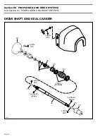
24,25,34, Drive Shaft, Carbon Ring and
Damper
Wear
Visually inspect shape of dampers for deforma-
tion or other damage. Ensure they are firmly re-
tained.
Inspect carbon ring and its contact surface. Check
for scoring, pitting, chipping or other evidence of
wear.
With a finger nail, feel contact surfaces of bearing
and seals. If any irregular surface is found, renew
drive shaft.
1. Carbon ring contact surface
2. Splines condition
3. Seal contact surface
Deflection
Excessive deflection could cause vibration and
damage to drive shaft splines, impeller, flywheel
or seal carrier.
Install drive shaft in V-blocks and set a dial gauge
in center of shaft. Slowly rotate shaft
; difference
between highest and lowest dial gauge reading is
deflection. Refer to the following illustration.
Maximum permissible deflection is 0.5 mm (.020
in).
MEASURING DRIVE SHAFT DEFLECTION
1. Dial gauge
2. V-blocks
19, Impeller
Identification
To identify the impellers refer to the following il-
lustration and chart.
1. Stamped part number
F01J14A
3
1
2
BOAT
MODEL
IMPELLER
P / N
MATERIAL
PITCH
SPORTSTER
271 000 470
Stainless
steel
Progressive
pitch
11° - 25°
CHALLENGER
271 000 620
Stainless
steel
Progressive
pitch
11° - 25°
SPEEDSTER
_
Stainless
steel
Progressive
pitch
_
F01J15A
1
2
F01J4LA
XXXXXXXXX
1
Summary of Contents for Challenger 5896
Page 1: ......
Page 2: ......
Page 3: ...219 100 044 0 0 0 1996 Shop Manual 0 R ...
Page 152: ...Section 08 ELECTRICAL Sub Section 03 IGNITION SYSTEM 08 03 2 ELECTRICAL BOX Sportster F04H11S ...
Page 154: ...Section 08 ELECTRICAL Sub Section 03 IGNITION SYSTEM 08 03 4 ELECTRICAL BOX Speedster F04H26S ...
Page 251: ...Section 11 HULL DECK Sub Section 01 COMPONENTS 11 01 5 F04L3IS Loctite 242 ...
Page 274: ......

