


Section 04
ENGINE
Sub-Section 05
(ROTARY VALVE)
04-05-4
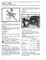
CLEANING
Discard all seals and O-rings.
Clean all metal components in a solvent.
Clean oil passages and make sure they are not
clogged.
Clean rotary valve shaft and inside of distance
sleeve.
INSPECTION
Inspect rotary valve cover for warpage. Small de-
formation can be corrected by surfacing with fine
sand paper on a surface plate. Surface part
against oiled sand paper.
Inspect bearings. Check for scoring, pitting, chip-
ping or other evidence of wear. Make sure plastic
cage (on bigger bearing) is not melted. Rotate
them and make sure they turn smoothly.
Check for presence of brass filings in gear hous-
ing.
Visually check gear wear pattern. It should be
even on tooth length all around. Otherwise it
could indicate a bent shaft, check deflection. Re-
place gear if damaged.
The inspection of rotary valve system should in-
clude the following measurements.
NOTE :
The following verifications can be
performed with engine in jet boat without
overhauling engine.
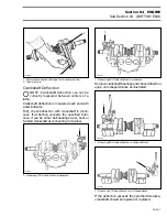
Rotary Valve / Cover Clearance
There is a choice of 2 measuring methods :
One with a 45
°
feeler gauge, the other one with
solder.
The clearance between the rotary valve and the
cover must be 0.30
±
0.05 mm (0.012
±
0.002 in).
NOTE :
If the clearance is below 0.25 mm
(0.010 in) this could create an overheating
situation and if the clearance is over 0.35 mm
(0.014 in) this could create a hard starting situa-
tion.
45
°
Feeler Gauge Method
Remove rotary valve cover and its O-ring.
Reinstall cover in place WITHOUT its O-ring and
torque screws to 20 N•m (15 lbf•ft).
Feeler gauge blade from 0.25 mm (.010 in) to 0.35
mm (.014 in) thickness should fit between rotary
valve and cover.
Insert feeler gauge blade through cover inlet ports
to verify clearance. At least verify clearance at 2
different places in each port.
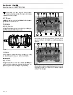
1. 45
°
feeler gauge
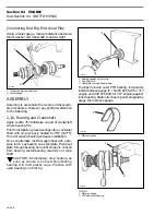
Solder Method
Remove rotary valve cover and its O-ring.
Use the following type of solder
:
– rosin core
– diameter
:
0.8 mm (0.032 in)
– electronic application (available at electronic
stores)
Install 2 short pieces (13 mm (1/2 in) long) of sol-
der directly on rotary valve, 1 above and 1 below
rotary valve gear. Apply grease to hold solder in
position.
Reinstall cover in place WITHOUT its O-ring and
torque screws to 20 N•m (15 lbf•ft).
Remove cover then clean and measure com-
pressed solder thickness, it must be within the
specified tolerance 0.30
±
0.05 mm (0.012
±
.002
in).
MEASUREMENTS
TOLERANCE
NEW PARTS
WEAR LIMIT
Rotary Valve / Cover
Clearance
0.25 - 0.35 mm
(.010 - .014 in)
0.35 mm
(.014 in)
Rotary Valve Shaft
Deflection
N.A.
0.08 mm
(.003 in)
'
'
F01D53A
1
Summary of Contents for Challenger 5896
Page 1: ......
Page 2: ......
Page 3: ...219 100 044 0 0 0 1996 Shop Manual 0 R ...
Page 152: ...Section 08 ELECTRICAL Sub Section 03 IGNITION SYSTEM 08 03 2 ELECTRICAL BOX Sportster F04H11S ...
Page 154: ...Section 08 ELECTRICAL Sub Section 03 IGNITION SYSTEM 08 03 4 ELECTRICAL BOX Speedster F04H26S ...
Page 251: ...Section 11 HULL DECK Sub Section 01 COMPONENTS 11 01 5 F04L3IS Loctite 242 ...
Page 274: ......