Section 08
ELECTRICAL
Sub-Section 03
(IGNITION SYSTEM)
08-03-12
IGNITION SYSTEM TESTING PROCEDURE, 787 ENGINE
General
NOTE :
On occasion a component will stati-
cally check good but in fact be defective. In
this instance, removing the original part and re-
placing it with a known good part is the most ac-
curate procedure.
The MPEM (Multi-Purpose Electronic Module) is
part of the ignition system as well as part of elec-
trical system. This section gives testing proce-
dure for ignition-related problems. For other type
of problems, refer to MPEM section.
CAUTION : Whenever replacing a compo-
nent in ignition system, check ignition
timing.
Spark occurrence can be checked with a tester
from Superex Canada Ltd P
/
N 15-785.
To perform verifications, a good quality multime-
ter such as Fluke 73 (P
/
N 529 022 000) can be
used.
When dealing with ignition problems, the follow-
ing items should be checked in this order
:
1. Spark occurrence
/
spark plug condition.
2. Battery condition.
3. MPEM supply fuse condition.
4. Electrical connections.
5. Engine stop
/
safety lanyard
6. MPEM
7. DC-CDI module
8. Magneto output.
9. Ignition coil output.
The first 5 items can be checked with common
automotive equipment. For item 6, refer to
MPEM section. For items 7,8 and 9, refer to the
following procedures.
MPEM (Multi-Purpose Electronic
Module)
ENGINE RPM LIMITER
A defective RPM limiter may cause the following
problems
:
• No spark.
• Misfiring
/
black fouled spark plugs.
• Uninterrupted spark when engine stop
/
safety
• lanyard
/
ignition switch is used.
• Incorrectly controlled engine maximum RPM.
To diagnose spark problems that might come
from the MPEM, first check that its BLACK wire
is perfectly grounded, then if there is no spark,
temporarily bypass the RPM limiter by discon-
necting the BLACK
/
RED
/GREEN wire coming
from engine magneto system. If everything now
works normally, the RPM limiter is defective and
the MPEM must be replaced.
If engine does not stop when using stop
/
safety
lanyard
/
ignition switch, ensure that BLACK
/
RED
/GREEN wire is well connected to MPEM, check
operation of all switches and if everything test
good, the MPEM is defective and must be re-
placed.
To check engine RPM limitation function, run en-
gine with shifter in forward or reverse position
and check its maximum speed. It should be
around 7200
RPM. Otherwise, the RPM limiter is defective and
the MPEM must be replaced.
If the engine maximum speed does not go over
3500 RPM, the problem might come from the
neutral switch. Refer to MPEM section.
Trigger Coil
STATIC TEST : CONTINUITY
1. Disconnect the stator
/
trigger coil plug at the
engine magneto cover. Connect the 6-pin mag-
neto test harness (P / N 295 000 136) at the
engine. DO NOT connect the other end at the
boat’s harness.
2. Connect the multimeter leads as shown (BK
/
YL to one meter lead, YL
/
WH to the other
lead). Resistance should be approximately 242
ohms (
±
10%).
'
-
Summary of Contents for Challenger 5896
Page 1: ......
Page 2: ......
Page 3: ...219 100 044 0 0 0 1996 Shop Manual 0 R ...
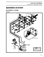
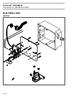
Page 152: ...Section 08 ELECTRICAL Sub Section 03 IGNITION SYSTEM 08 03 2 ELECTRICAL BOX Sportster F04H11S ...
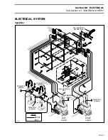
Page 154: ...Section 08 ELECTRICAL Sub Section 03 IGNITION SYSTEM 08 03 4 ELECTRICAL BOX Speedster F04H26S ...
Page 251: ...Section 11 HULL DECK Sub Section 01 COMPONENTS 11 01 5 F04L3IS Loctite 242 ...
Page 274: ......

