Section 08
ELECTRICAL
Sub-Section 03
(IGNITION SYSTEM)
08-03-8
Summary Table for Bombardier
Ignition Tester
Ignition System Components
Resistance Measurement
As an alternate method, ignition components can
be checked with an ohmmeter (preferably a digital
one). Proceeding by elimination, check ignition
system generator coil then ignition coil
/
ignition
module.
NOTE :
CDI module is part of ignition coil
and therefore, there is no probe point to spe-
cifically test primary winding of ignition coil. Only
the secondary winding can be measured.
Disconnect connectors at ignition coil and magne-
to connector at engine. Connect the 4-pin magne-
to test harness (P / N 295 000131) at the engine.
Do not connect the other end at the boat’s har-
ness. Check resistance between each terminal
with a high-sensitivity ohmmeter. Refer to the fol-
lowing table for values and wire colors.
NOTE :
An ignition coil with good resistance
measurement can still be faulty. Voltage leak
can occur at high voltage level which is not detect-
able with an ohmmeter.
NOTE :
A short circuit will read 0 ohm (or
close to) on ohmmeter.
The spark plug caps must be removed from high
tension cables, because they are resistor caps.
The cap resistance is 4.5-5.5 K ohms.
1. Resistor cap
2. High-tension cable
IGNITION TIMING, 717 ENGINE
This section is mainly divided in 2 parts, the first
one using a top dead center (TDC) gauge to verify
PTO Flywheel Timing Mark Position. The second
one using a stroboscopic timing light to check Ig-
nition Timing.
Flywheel timing mark position verification is re-
quired to :
1. Troubleshoot a missing or broken magneto fly-
wheel woodruff key.
2. Troubleshoot a magneto flywheel correspond-
ing to a different engine type.
3. Scribe the timing mark on a new service PTO
flywheel.
Always verify PTO flywheel timing mark position
before checking ignition timing.
Verifying PTO Flywheel Timing Mark
Position
1. Disconnect MAG side spark plug wire and con-
nect wire to grounding device then remove
spark plug.
2. Remove PTO flywheel guard.
Test to
perform
Tester
wires
Component wires
Switch Dial
Ignition
system
generator
coil output
N
BLACK / RED
of magneto harness
LOW
85
P
BLACK
of magneto harness
Ignition
coil
output
N
Tester adapter
on MAG spark
plug cable
LOW
35
P
Engine ground
MAGNETO
PART NAME
WIRE COLOR
RESISTANCE
(OHM) (
Ω
)
Ignition
system
generator
coil
BLACK with
BLACK / RED
40-76
'
'
IGNITION COIL
PART NAME
WIRE COLOR
RESISTANCE
(OHM) (
Ω
)
Secondary
winding
End of each
spark plug
cable, spark
plug caps
removed
9-15 k
'
A00E0QA
1
2
Summary of Contents for Challenger 5896
Page 1: ......
Page 2: ......
Page 3: ...219 100 044 0 0 0 1996 Shop Manual 0 R ...
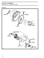
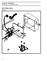
Page 152: ...Section 08 ELECTRICAL Sub Section 03 IGNITION SYSTEM 08 03 2 ELECTRICAL BOX Sportster F04H11S ...
Page 154: ...Section 08 ELECTRICAL Sub Section 03 IGNITION SYSTEM 08 03 4 ELECTRICAL BOX Speedster F04H26S ...
Page 251: ...Section 11 HULL DECK Sub Section 01 COMPONENTS 11 01 5 F04L3IS Loctite 242 ...
Page 274: ......

