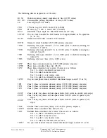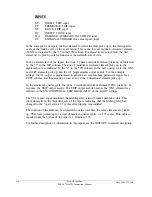
50N1
50N2
50N3
Z1DG
Z2DG
Z3DG
TDUR
52BT
ZONE3
67NE
67PE
32QE
32IE
Zone 1 residual instantaneous-overcurrent (0.25-50,000 primary amperes)
Zone 2 residual instantaneous-overcurrent (0.25-50,000 primary amperes)
Zone 3 residual instantaneous-overcurrent (0.25-50,000 primary amperes)
Zone 1 delay for ground faults (0-60 cycles in quarter cycle steps)
Zone 2 delay for ground faults (0-2000 cycles in quarter cycle steps)
Zone 3 delay for ground faults (0-2000 cycles in quarter cycle steps)
Minimum Trip Duration timer (0-2000 cycles in quarter cycle steps)
52B time delay (0.5 to 10,000 cycles in quarter cycle steps)
Zone 3 direction (F = forward or R = reverse)
Do you want directional torque control for the residual instantaneous-overcurrent
elements? (Y or N)
Do you want directional torque control for the phase instantaneous-overcurrent
elements? (Y or N)
Do you want negative-sequence directional supervision of the ground-overcurrent
elements? (Y or N)
Do you want zero-sequence current-polarization for the directional element
enabled? (Y or N)
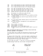
TIME1
Timeout for PORT 1 (0-30 minutes)
TIME2
Timeout for PORT 2 (0-30 minutes)
AUTO
Autoport (PORT 1 or 2, or 3 for both PORTS 1 and 2)
RINGS
The number of rings after which the modem connected to PORT 1 answers (1-30
rings)
Refer to the functional description and be sure the settings you choose result in relay
performance appropriate to your application.
As you enter settings, they are compared with setting limits above. Then the relay computes
internal settings from your entries and checks to ensure that they fall within the specified
range.
For example, let CTR= 1000 and 50N1 = 1. Each of these settings is admissible alone, but
together they result in a secondary pickup setting of 1 mA, which is out of range. Internal
setting error messages indicate out-of-range settings after you enable the new settings (refer to
the Specifications for the secondary ranges of the relay elements).
The AUTO setting selects PORT 1, 2, or both of the two serial ports for automatically
transmitted messages. The table below shows the effect of each possible setting:
Auto
Setting
Automatic Message
Destination Port
1
1
2
2
3
1 and 2
3-22
Commands and Serial Communication
SEL-267D/167D Instruction Manual
Date Code 920326
Summary of Contents for SEL-167D
Page 3: ......
Page 6: ......
Page 8: ......
Page 9: ......
Page 10: ......
Page 11: ......
Page 51: ...LOGIC DIAGRAMS Date Code 920326 Specifications SEL 267D 167D Instruction Manual 2 31 ...
Page 52: ...Date Code 920326 Specifications 2 32 SEL 267D 167D Instruction Manual ...
Page 53: ...Date Code 920326 Specifications SEL 267D 167D Instruction Manual 2 33 ...
Page 54: ...Date Code 920326 Specifications SEL 267D 167D Instruction Manual 2 34 ...
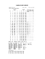
Page 88: ...SAMPLE EVENT REPORT ...
Page 114: ......
Page 115: ......


