<ENTER>
to check these pickups. Apply current to one phase (close in magnitude to the
set pickup) and observe the pickup and dropout of the elements.
Testing the Input Circuits
1.
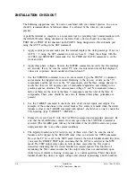
Use the TARGET command to set the LEDs to follow the contact inputs. Type
TAR 5
<ENTER>.
2.
Apply control voltage to each input and observe that the corresponding target LED turns
on. Event reports should be triggered whenever you energize the DT, PT, BT, and ET
inputs.
Testing the Serial Ports
The Initial Checkout procedure assumes that you connect a terminal to PORT 2. Set the baud
rate of PORT 1 to the same value as that of PORT 2 and switch your terminal from PORT 2
to PORT 1. Make sure you can communicate through this port. If your relay is equipped
with front and rear panel serial ports, ensure that both ports operate properly.
Testing the IRIG-B Time Code Input
1.
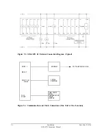
Connect a source of demodulated IRIG-B time code to the Auxiliary Port of the relay
with a series resistor to monitor the current. Adjust the source to obtain an
"
ON
"
current of about 10 mA.
2.
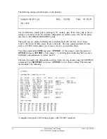
Execute the IRIG command, and make sure the SEL-267D relay clock displays the
correct date and time.
Note:
For a convenient, inexpensive test of the IRIG-B port, use a recording of the IRIG-B
signal passed through a simple demodulator. Please contact the factory for further
details.
Testing the Power Supply Voltages
1.
Execute the STATUS command and inspect the voltage readings for the +5 and ±15
volt supplies.
2.
At the Auxiliary Port, use a voltmeter to read the +5 and ±12 volt outputs. The 12 volt
outputs are derived from the 15 volt supplies using three-terminal regulators.
3.
Compare the +5 volt readings from the status report and the voltmeter. The voltage
difference should be less than 50 mV, and both readings should be within 0.15 volts of
five volts.
4.
The 12 volt supplies should be within 0.5 volt of their nominal values.
6-8
Maintenance and Testing
SEL-267D/167D Instruction Manual
Date Code 920326
Summary of Contents for SEL-167D
Page 3: ......
Page 6: ......
Page 8: ......
Page 9: ......
Page 10: ......
Page 11: ......
Page 51: ...LOGIC DIAGRAMS Date Code 920326 Specifications SEL 267D 167D Instruction Manual 2 31 ...
Page 52: ...Date Code 920326 Specifications 2 32 SEL 267D 167D Instruction Manual ...
Page 53: ...Date Code 920326 Specifications SEL 267D 167D Instruction Manual 2 33 ...
Page 54: ...Date Code 920326 Specifications SEL 267D 167D Instruction Manual 2 34 ...
Page 88: ...SAMPLE EVENT REPORT ...
Page 114: ......
Page 115: ......

