background image

System  Does  Not  Respond  to  Faults

Relay  improperly  set.  Review  your  settings  with  the  SET  and  LOGIC  commands.

Improper  test  set  settings.

CT  or  PT  input  cable  wiring  error.  Check  input  voltages  and  currents  with  METER
command  and  TRIGGER  and  EVENT  sequence.

Analog  input  cable  between  transformer  and  main  board  loose  or  defective.

Check  built-in-test  status  with  STATUS  command.

Terminal  Displays  Meaningless  Characters

Baud  rate  incorrectly  set.  Check  terminal  configuration:  see  COMMANDS  AND
SERIAL  COMMUNICATIONS  section.

Self-Test  Failure:  +5  Volts

Power  supply  +5  volt  output  out  of  tolerance.  See  STATUS  command.

A/D  converter  failure.

Self-Test Failure: + 15 Volts

Power  supply  +  15  volt  output  out  of  tolerance.  See  STATUS  command.

A/D  converter  failure.

Self-Test Failure: -15 Volts

Power  supply  -15  volt  output  out  of  tolerance.  See  STATUS  command.

A/D  converter  failure.

Self-Test Failure: Offset

Offset  drift  (adjust  offsets).

A/D converter drift.

Loose  ribbon  cable  from  transformers  to  main  board.

Date  Code  940208

Maintenance  and  Testing

SEL-267D/167D  Instruction  Manual

6-11

Summary of Contents for SEL-167D

Page 1: ...67D PHASE AND GROUND DIRECTIONAL OVERCURRENT RELAY WITH RECLOSER AND FAULT LOCATOR INSTRUCTION MANUAL SCHWEITZER ENGINEERING LABORATORIES 2350 NE HOPKINS COURT PULLMAN WA 99163 5603 TEL 509 332 1890 FAX 509 332 7990 ...

Page 2: ...ected by the United States Copyright Law and International Treaty provisions All rights are reserved You may not copy alter disassemble or reverse engineer the software You may not provide the software to any third party The schematics and parts lists are provided solely for the purpose of product maintenance Copyright SEL 1992 All rights reserved Printed in USA ...

Page 3: ......

Page 4: ...es related to the shipment of defective units back to SEL or the provision of a substitute unit to the customer are the responsibility of the customer This expense may include but is not limited to freight insurance Customs clearance and duties All expenses related to the shipment of repaired units back to customers or the provision of a new unit to the customer will be borne by SEL PRODUCT UPGRAD...

Page 5: ...ot manufactured by SEL Such equipment and products may be covered by a warranty issued by the respective manufacturer This warranty is in lieu of any other warranties express or implied including without limitation any warranty of merchantability or fitness for a particular purpose and is in lieu of any and all other obligations or liability of SEL Under no circumstances shall SEL be liable for an...

Page 6: ......

Page 7: ...ACB phase rotation option references made in the instruction manual to voltage and current phase angle should be noted accordingly The firmware identification number FID may be used to verify whether your relay was ordered with ABC or ACB rotation All current and voltage inputs are connected to the SEL relay rear panel as shown in the instruction manual Date Code 930719 SEL Relay Addendum A 1 ...

Page 8: ......

Page 9: ......

Page 10: ......

Page 11: ......

Page 12: ... 6 Definition of Logic Variables 2 10 Logic Description 2 11 Intermediate Logic 2 13 Relay Word 2 14 Output Equations 2 15 Reclosing Relay 2 17 Targets 2 17 Self Tests 2 18 Setting Procedure 2 20 Event Report 2 21 Fault Locator 2 21 Directional Elements 2 24 Time Overcurrent Elements and Curves 2 25 Time Overcurrent Curve Equations 2 36 Logic Diagrams 2 31 COMMUNICATIONS Introduction 3 1 Serial Po...

Page 13: ...Connections 5 1 Secondary Circuits 5 1 Control Circuits 5 2 Communications Circuits 5 2 Jumper Selection 5 2 EIA RS 232 C and IRIG B Installation 5 3 Installation Checkout 5 6 MAINTENANCE AND TESTING Initial Checkout 6 1 Functional Tests 6 5 Calibration 6 9 Troubleshooting Guide 6 9 Troubleshooting Table 6 9 APPENDICES Appendix A Firmware Versions in this Manual Appendix A 1 Appendix B Parts Place...

Page 14: ...ram 2 5 Figure 2 2 Programmable Trip Logic Diagram 2 16 Figure 2 3 Moderately Inverse Curves 2 Figure 2 4 Inverse Curves 2 Figure 2 5 Very Inverse Curves 2 Figure 2 6 Extremely Inverse Curves 2 Logic Diagrams 2 Figure 5 1 9 Pin Connector Pin Number Convention 5 3 Figure 5 2 SEL 267D External Ac Current and Voltage Connections 5 7 Figure 5 3 SEL 267D Dc External Connection Diagram Typical 5 8 Figur...

Page 15: ...Date Code 920320 Table of Contents i SEL 267D 167D Instruction Manual INTRODUCTION TABLE OF CONTENTS Getting Started 1 1 Overview 1 1 Basic Protective Capabilities 1 2 General Information 1 3 ...

Page 16: ...lied to protect transmission subtransmission and distribution lines The SEL 267D relay is intended for use on grounded systems with open delta connected potential transformers Use the SEL 267 relay where wye connected potential transformers are applied The features of the SEL 267D relay include Directional Overcurrent Protection for Phase and Ground Faults Versatile User Programmable Logic Three S...

Page 17: ...ent must be exceeded for faults in either direction before fault direction is declared Each of the directionally supervised outputs of the overcurrent elements drive timers The Relay Word contains the instantaneous nondirectional outputs 50P1 50P2 50P3 the instantaneous directional outputs 67P1 67P2 67P3 and the definite time delayed outputs Z1PT Z2PT Z3PT The direction of 67P3 Z3PT may be reverse...

Page 18: ... initiated or cancelled for any conditions recorded in the Relay Word and is accomplished by programming the Reclose Initiate and Reclose Cancel masks GENERAL INFORMATION Communications functions provide remote and local examination of a wide range of data including the voltages and currents presented to the instrument relay settings and a history of the twelve most recent events Relay settings ma...

Page 19: ...elay retains the twelve most recent event reports A user may recall any of these reports on command Phasor diagrams of the voltages and currents showing prefault fault and postfault conditions can be constructed from the fault report This accurate information is useful in verifying short circuit and load flow calculations verifying transmission line constants and measuring voltage and current unba...

Page 20: ...ime Overcurrent Curve Equations 2 26 Logic Diagrams 2 31 TABLES Table 2 2 Input Parameters 2 7 Table 2 3 Relay Outputs 2 9 Table 2 4 Relay Word 2 14 Table 2 5 Relay Word Bit Summary 2 15 Table 2 6 Front Panel Target Conditions for Illumination 2 17 Table 2 7 Power Supply Self Test Limits 2 18 Table 2 8 Self Test Summary 2 20 FIGURES Figure 2 1 Hardware Block Diagram 2 5 Figure 2 2 Programmable Tri...

Page 21: ... 20 60 Vdc 12 watts 125 250 Volt 85 350 Vdc or 85 264 12 watts Routine tested V I inputs 2500 Vac for 10 seconds Other 3000 Vdc for 10 seconds excludes RS 232 C and time code input IEEE C37 90 SWC test type tested IEC 255 6 interference test type tested IEC 255 5 0 5 joule 5000 volt test type tested Type tested in field from a wave antenna driven by 20 watts at 150 MHz and 450 MHz randomly keyed o...

Page 22: ...rent improving accuracy for high resistance faults All metered quantities are displayed in primary units Voltage Phase phase voltages are measured scaled to primary and displayed upon command Each phase current is measured scaled to primary and displayed on command Calculated phase to phase currents are also displayed Current demand is computed with a 5 to 60 minute time constant To see the curren...

Page 23: ...ckup 1 A to 25 times 51P pickup Timers are provided for each zone Zone 1 Timer 0 60 cycles in 0 25 cycle steps Zone 2 Timer 0 2000 cycles in 0 25 cycle steps Zone 3 Timer 0 2000 cycles in 0 25 cycle steps Ground Overcurrent Secondary Values 51N Residual time overcurrent element Selectable curve shape 4 curves Time dial 0 50 to 15 00 in steps of 0 01 Pickup 0 25 to 6 3 A 0 05 A 2 of setting 50N1 50...

Page 24: ...irectional element Angle MTA setting 47 90 in 1 steps Sensitivity Proportional to 51P pickup for 4 A 51PP 12 6 A 0 35 VA at 12 6 A pickup at MTA 0 11 VA at 4 0 A pickup and below at MTA Zero Sequence Directional Element Current polarization Angle 0 Sensitivity 0 5 A x 51N pickup setting at 0 in units of residual amps squared and Ipol 0 5 A Three shot reclosing relay 79OI1 open interval 1 79OI2 ope...

Page 25: ...m access memory for data storage and EEPROM electrically erasable programmable ROM for storing the relay settings The EEPROM saves settings even during power loss Input output I O devices connected to the microcomputer bus provide for the control of the output relays targets and monitor inputs such as the state of the breaker 52A contact Other I O devices provide communications for setting reporti...

Page 26: ...mbines with the previous value renamed Q to form a Cartesian coordinate pair This pair represents the input signal as a phasor P Q The relay processes these phasor representations of the input signals INPUTS AND OUTPUTS Serial Interfaces The SEL 267D relay is equipped with two EIA RS 232 C serial communication ports PORT 2 has 9 pin connectors on both the front and rear panels designated PORT 2F a...

Page 27: ... serial data interface Input Power Terminals marked and should be connected to a source of control voltage Polarity of dc power is unimportant Power requirement is about 12 watts Terminal marked GND should be wired to the relay rack ground reference for grounding the instrument frame Contact Inputs Six input circuits are provided They are listed below Direct Trip Direct Close Permissive Trip 52A M...

Page 28: ...until the 52A input asserts or until the reclosing relay reset interval expires whichever occurs first No event report is triggered The CLOSE command has the same effect as the DC input Permissive Trip PT The PT input is normally used in permissive transfer tripping schemes When it asserts an event is triggered and additional tripping conditions are allowed as selected in the logic setting procedu...

Page 29: ...conditions are grouped as follows unconditional subject to PT input assertion subject to the absence of BT input and subject to the breaker being open The TRIP output never closes for less than the duration of the TDUR setting After this interval it opens when the fault condition ceases and the over current elements in Relay Word Row 1 have dropped out or when the TARGET RESET button is pressed CL...

Page 30: ...connected in an open delta configuration The relay contains a set of three input transformers connected in delta The nominal voltage rating is 115 volts line to line Current Inputs The rating of the input current transformers in the relay is 5 amperes nominal 15 amperes continuous and 500 amperes for one second DEFINITION OF LOGIC VARIABLES The output relay states of the SEL 267D relay depend on t...

Page 31: ...ectional Nondirectional 32PQF forward 32PQR reverse 32QF forward 32QR reverse 32IF forward 32IR reverse Timers Z1DG Z2DG Z3DG Z1DP Z2DP Z3DP 52BT 79OI1 79OI2 79OI3 79RS Zone 1 ground timer timeout operated by 67N1 Z1DG setting Zone 2 ground timer timeout operated by 67N2 Z2DG setting Zone 3 ground timer timeout operated by 67N3 Z3DG setting Zone 1 phase timer timeout operated by 67P1 Zone 2 phase ...

Page 32: ...s torque control for 51N 51PTC Selects torque control for 51P Contact Inputs DT Direct trip PT Permissive transfer trip BT Block trip DC Direct close 52 Circuit breaker monitor EXT External trigger for event report Contact Outputs TRIP Circuit breaker trip CLOSE Circuit breaker close A1 Programmable output 1 A2 Programmable output 2 A3 Programmable output 3 A4 Programmable output 4 ALARM System al...

Page 33: ... 67P3 Z3DP Z2PT 67P2 Z2DP Z1PT 67P1 Z1DP Z3GT 67N3 Z3DG Z2GT 67N2 Z2DG Z1GT 67N1 Z1DG Zone 3 phase fault Zone 2 phase fault Zone 1 phase fault Ground fault Phase fault Phase forward direction Phase reverse direction if ZONE3 is forward if ZONE3 is reverse Zone 3 directional phase overcurrent element reversible Zone 2 directional phase overcurrent element Zone 1 directional phase overcurrent elemen...

Page 34: ...You can program the bits in these masks with the LOGIC command Table 2 4 Relay Word 51NP 50N1 50N2 50N3 51PP 50P1 50P2 50P3 DFP 67N1 67N2 67N3 DFG 67P1 67P2 67P3 51NT Z1GT Z2GT Z3GT 51PT Z1PT Z2PT Z3PT ALRM TRIP TC DT 52BT 52AT TOCP DCTH Table 2 5 Relay Word Bit Summary on the following page explains the meaning of each bit in the Relay Word The use of the Relay Word and programmable masks provide...

Page 35: ...ectional overcurrent element directional as enabled Direction forward ground fault Zone 1 phase directional overcurrent element directional as enabled Zone 2 phase directional overcurrent element directional as enabled Zone 3 phase directional overcurrent element directional as enabled Ground time overcurrent trip directional as enabled Zone 1 timeout ground Zone 2 timeout ground Zone 3 timeout gr...

Page 36: ...ng M T O mask for trip with breaker open Then TRIP R MTU R MPT PT R MTB NOT BT R MTO 52BT close TRIP contact TRIP open TRIP contact NOT TRIP NOT Any element in Relay Word Row 1 picked up TARGET RESET button pushed Trip Duration timer expired TDUR close CLOSE contact DC 79OI1 79OI2 79OI3 CLOSE command NOT 52A open CLOSE contact NOT CLOSE 79RS Al R MA1 A2 R MA2 A3 R MA3 A4 R MA4 The symbol indicates...

Page 37: ...r reclose initiation and MRC is the mask for reclose cancellation The open intervals do not begin until the TRIP output and 52A input deassert Since the TRIP output never asserts for less than the TDUR timer setting the open interval may start several milliseconds after the fault has actually cleared and the breaker opened Reclose is automatically cancelled when the circuit breaker is observed to ...

Page 38: ...any change in self test status The relay closes the ALARM contacts after any self test fails When it detects certain failures the relay disables the breaker control functions and places the relay output driver port in an input mode No outputs may be asserted when the instrument is in this configuration The relay runs all self tests on power up and before enabling new settings During normal operati...

Page 39: ... closes the ALARM output relay contacts Analog to Digital Converter The analog to digital converter A D changes voltage signals derived from power system voltages and currents into numbers for processing by the microcomputer The A D test verifies converter function by checking conversion time The test fails if conversion time is excessive or a conversion starts and never finishes There is no warni...

Page 40: ... contact assertion W F NO YES NO YES no ALARM contact assertion permanent contact assertion 15 V W F NO YES NO NO no ALARM contact assertion permanent contact assertion W F CHANNEL OFFSETS NO NO NO NO no ALARM contact assertion one second contact pulse MASTER OFFSET W F NO NO NO NO no ALARM contact assertion one second contact pulse SETTING PROCEDURE You may enter the settings for the SEL 267D rel...

Page 41: ...puted from the time the first report is triggered by the fault and the time the second report is triggered by the trip The reported event time corresponds to the 16th quarter cycle of the event report in all cases The event report contains voltages currents system settings and other information It is described in detail in the EVENT REPORTING section Execution of the CLOSE command does not trigger...

Page 42: ...e meaning that for these events additional reports are generated even while any or all relay elements remain picked up This strategy permits for example the recording of fault clearing even when it occurs long after the initial event report is completed The fault location is always determined for event records in which any triggering relay elements are picked up providing they are not picked up in...

Page 43: ...Ifmax 1 5 x Ifmed THEN Single phase ELSE IF Ifmed 1 5 x Ifmin THEN Two phase ELSE IF none of the above THEN Three phase This algorithm is largely immune to load and system grounding variations Once the fault type is determined the fault locator employs the Takagi algorithm to locate the fault Using both prefault and fault data it compensates for the errors introduced by fault resistance in the pre...

Page 44: ...2027 0 98 times the actual location or about 2 miles short for a fault at the far end of a 100 mile line When compensation using shunt reactors is employed and when the measured current equals the reactor current plus the line current the shunt reactors reduce the errors due to neglecting the shunt capacitance of the transmission line 100 3100 2 3 14159 0 2027 radians DIRECTIONAL ELEMENTS The SEL ...

Page 45: ...ny masks The TOCP time overcurrent pickup bit in the Relay Word is formed by either the 51N pickup or 51P pickup or both 51NP 51PP You can select the time dial and the curve shape with the setting procedure Four curve shapes are available The curves and equations are provided at the end of this section The 51N and 51P characteristic is formed by a recursive sum of the magnitude or magnitude square...

Page 46: ...Let t operating time in seconds TD time dial setting M multiples of pickup Curve 1 Moderately Inverse Curve 2 Inverse Curve 3 Very Inverse Curve 4 Extremely Inverse 2 26 Specifications SEL 267D 167D Instruction Manual Date Code 920326 ...

Page 47: ...Figure 2 3 Time Overcurrent Element Moderately Inverse Time Characteristic Curve 1 Date Code 920326 Specifications SEL 267D 167D Instruction Manual 2 27 ...

Page 48: ...Multiples of Pickup Figure 2 4 Time Overcurrent Element Inverse Time Characteristic Curve 2 2 28 Specifications SEL 267D 167D Instruction Manual Date Code 920326 ...

Page 49: ...Multiples of Pickup Figure 2 5 Time Overcurrent Element Very Inverse Time Characteristic Curve 3 Date Code 920326 Specifications SEL 267D 167D Instruction Manual 2 29 ...

Page 50: ...Figure 2 6 Time Overcurrent Element Extremely Inverse Time Characteristic Curve 4 Multiples of Pickup 2 30 Specifications SEL 267D 167D Instruction Manual Date Code 920326 ...

Page 51: ...LOGIC DIAGRAMS Date Code 920326 Specifications SEL 267D 167D Instruction Manual 2 31 ...

Page 52: ...Date Code 920326 Specifications 2 32 SEL 267D 167D Instruction Manual ...

Page 53: ...Date Code 920326 Specifications SEL 267D 167D Instruction Manual 2 33 ...

Page 54: ...Date Code 920326 Specifications SEL 267D 167D Instruction Manual 2 34 ...

Page 55: ...L COMMUNICATIONS TABLE OF CONTENTS Introduction 3 1 Serial Port Connections and Configurations 3 2 Communications Protocol 3 2 Command Characteristics 3 4 Command Descriptions 3 6 Command Summary 3 23 TABLES Table 3 1 Hexadecimal Binary Conversion 3 13 Table 3 2 Target LED Assignment 3 15 ...

Page 56: ...the TRIGGER command Assertion of the TRIP output No event record is made for assertion of the DIRECT CLOSE input assertion of the 52A input or execution of the CLOSE command The relay responds to commands spanning all functions of the instrument such as metering setting the clock and control operations Two access levels with separate passwords protect against unauthorized access through the commun...

Page 57: ...ications PORT 1 and the Auxiliary Input for demodulated IRIG B time code input remain on the relay rear panel Communications port baud rate jumpers are located along the front edge of the circuit board To select a baud rate for PORT 1 or PORT 2 remove the relay front panel The jumpers are Carefully move the jumpers using needle nosed pliers Available rates are 300 600 1200 2400 4800 and 9600 baud ...

Page 58: ... ASCII code to the relay 3 The relay indicates the volume of data in its received data buffer by an XON XOFF protocol XON ASCII hex 11 is transmitted by the relay when the buffer drops below full The relay also asserts the RTS output XOFF ASCII hex 13 is transmitted when the buffer fills above 3 4 full The relay deasserts the RTS output when the buffer is approximately 95 full Automatic transmitti...

Page 59: ...anging settings may be executed only from Access Level 2 You may enter Access Level 2 using the 2ACCESS command and the second password The Level 2 password is factory set to TAIL and may be changed with the PASSWORD command XON CONTROL Q XOFF CONTROL S CAN CONTROL X hold down the Control key and press Q hold down the Control key and press S hold down the Control key and press X Startup After the ...

Page 60: ...contact for about one second indicating an attempt at Level 2 Access Enter the proper password e g TAIL when you receive the second password prompt After you enter the second password the relay opens access to Level 2 as indicated by the following message and the Level 2 prompt Any Level 1 or Level 2 command may be executed from this prompt Command Format Commands consist of three or more characte...

Page 61: ...e shown below The prompt indicates that you have reached Access Level 1 After three successive failed access attempts the ALARM contact is pulsed closed for one second This feature can be used to alert operations personnel that possible unauthorized access is being attempted if the ALARM contact is connected to a monitoring system such as SCADA Access Level 1 Commands 2ACCESS Use 2ACCESS to contin...

Page 62: ...ameter n is 1 for the most recent event and 12 for the oldest event stored in the relay memory If n is not specified the report defaults to one To inspect the newest report type EVENT 1 ENTER or EVE ENTER The report provides the relay identifier string date and time the event occurred The next part of the event report displays eleven cycles of data for the five current channels IPOL IR IA IB and I...

Page 63: ...he date time and type of event for each of the twelve most recent events If the event is a fault the distance duration current and fault targets if the fault caused a trip are also shown An example of the display is provided below Note that only four events have occurred since the relay was set or powered on Each event report is time tagged to the nearest quarter cycle 4 17 ms and referenced to th...

Page 64: ...TYPE For events other than faults the TYPE indication is either TRIP or EXT The TYPE shows TRIP when the SEL 267D relay generates an event report in response to assertion of the TRIP output which results from execution of the OPEN command during no fault conditions For all other events TYPE shows EXT indicating a report generated in response to some external stimulus such as the assertion of the E...

Page 65: ... time An example of a successful read is shown below If no time code signal is present at the AUX port or if the time code cannot be successfully decoded the relay sends the error message IRIGB DATA ERROR An unsuccessful read causes the following output Note When the relay is connected to a time code signal via the AUX port it is normally unnecessary to synchronize using this command the relay syn...

Page 66: ...and resets the targets to the Relay Targets TAR 0 The terminal displays the relay I D date and time Use this command when you finish communicating with the SEL 267D relay to prevent unauthorized access Note that control returns to Access Level 0 automatically after a settable interval of no activity See the TIME1 and TIME2 settings of the SET command SHOWSET Use SHOWSET to inspect the settings of ...

Page 67: ... Row 1 of any column 51NP 50N1 50N2 50N3 51PP 5OP1 5OP2 5OP3 Row 2 of any column DFP 67Nl 67N2 67N3 DFG 67Pl 67P2 67P3 Row 3 of any column 51NT Z1GT Z2GT Z3GT 51PT ZlPT Z2PT Z3PT Row 4 of any column ALRM TRIP TC DT 52BT 52AT TOCP DCTH Logic settings appear in hexadecimal format The following table shows the equivalencies between hexadecimal hex and binary numbers to facilitate examination of the l...

Page 68: ...0110 0110 Now build row 2 of the Relay Word for mask MA1 as follows DFP 67N1 67N2 67N3 DFG 67P1 67P2 67P3 0 1 1 0 0 1 1 0 6 6 STATUS The STATUS command allows inspection of the self test status The relay also automatically executes this command whenever a self test enters a warning or failure state transmitting a STATUS report to the port selected for automatic transmissions see AUTO setting of th...

Page 69: ... and 0 8 and 1 2 volts for the 15 volt supplies The last two rows report status for five tests If a RAM or ROM test fails the IC socket number of the defective part is indicated in place of OK The A D self test checks the A D conversion time If it exceeds a threshold the test fails and protective functions are disabled The MOF test checks the offset in the MUX PGA A D circuit when a grounded input...

Page 70: ...and self test failures It does not assert for the SET LOGIC PASSWORD and DATE commands This differs from the ALARM output relay which asserts for all the above conditions The optional command parameter k selects the number of times the target data are repeatedly displayed for a given choice of parameter n To see a series of ten readings of Relay Word Row 4 type TARGET 4 10 ENTER Be sure to return ...

Page 71: ...the just triggered record after a short delay and a summary of the record is displayed The TRIGGER command is useful when inspecting phasor voltages and currents When the SEL 267D relay is first installed execute the TRIGGER command draw the phasors the EVENT REPORTING section explains how to do this and check for the proper polarity and phase sequence of the inputs Event records may also be gener...

Page 72: ...rip input asserted Mask for trip with block trip input deasserted Mask for trip with breaker open Mask for A1 relay control Mask for A2 relay control Mask for A3 relay control Mask for A4 relay control Mask for reclose initiate Mask for reclose cancel The logic programming procedure requires entry of changes to the mask or pressing ENTER to indicate no change Each of the masks listed above is spli...

Page 73: ... to change any member of a group all eight members must be input even if no change is needed for some members If an error occurs during input of new data the existing settings and question mark prompt are redisplayed to allow corrections An example below shows the removal of the Z3PT bit from the MTU logic mask 3 18 Commands and Serial Communication SEL 267D 167D Instruction Manual Date Code 92032...

Page 74: ... Answering Y ENTER yields a second prompt Are you Sure Y N Answering Y ENTER again causes the TRIP output relay to close as described above Answering N ENTER to either prompt aborts the OPEN command with the message Aborted The OPEN command aborts unless the remote open close jumper JMP104 is in place on the main circuit board PASSWORD 1 or 2 password PASSWORD allows you to inspect or change exist...

Page 75: ...swering prompting messages with new data or pressing ENTER to indicate no change When all data are provided the new settings are displayed and a prompt issued requesting your approval to enable the SEL 267D relay with the new settings When you complete all desired setting changes it is not necessary to scroll through the remaining settings Type END ENTER after the last setting change to proceed to...

Page 76: ...me dial 0 5 15 Phase time overcurrent curve index Choices are as follows Use 1 to select a moderately inverse curve Use 2 to select an inverse curve Use 3 to select a very inverse curve Use 4 to select an extremely inverse curve Do you want phase time overcurrent directional torque control Y or N Zone 1 phase overcurrent element pickup 0 25 50 000 primary amperes Zone 2 phase overcurrent element p...

Page 77: ... enabled Y or N TIME1 Timeout for PORT 1 0 30 minutes TIME2 Timeout for PORT 2 0 30 minutes AUTO Autoport PORT 1 or 2 or 3 for both PORTS 1 and 2 RINGS The number of rings after which the modem connected to PORT 1 answers 1 30 rings Refer to the functional description and be sure the settings you choose result in relay performance appropriate to your application As you enter settings they are comp...

Page 78: ...settings The logic settings are shown in hexadecimal format for each mask Shows self test status Shows data and sets target lights as follows TAR 0 Relay Targets TAR 1 RELAY WORD 1 TAR 2 RELAY WORD 2 TAR 3 RELAY WORD 3 TAR 4 RELAY WORD 4 TAR 5 Contact Inputs TAR 6 Contact Outputs TAR R Clears targets and returns to TAR 0 Be sure to return to TAR 0 when done so LEDs display fault targets Shows or s...

Page 79: ...ets field indicates any combination of the following P1 Zone 1 phase fault P3 Zone 3 phase fault G1 Zone 1 ground fault 63 Zone 3 ground fault P2 Zone 2 phase fault 51P Phase time overcurrent trip G2 Zone 2 ground fault 51N Residual time overcurrent trip R1 X1 R0 X0 Primary series impedance settings for transmission line LL Line length corresponding to specified line impedances ROS XOS Zero sequen...

Page 80: ... 267D 167D Instruction Manual EVENT REPORTING TABLE OF CONTENTS Introduction 4 1 Example Event Report 4 2 Interpretation of Voltage and Current Data 4 3 Relay Elements Status Indicators 4 5 Firmware Identification 4 7 Sample Event Report 4 8 ...

Page 81: ...ault conditions may be constructed It also contains status points spanning the states of all relay elements inputs and outputs These are useful in reviewing fault duration relay element responses arrival time of transfer trip signalling with respect to local relay response etc The full report is not transmitted automatically due to its length about one page You may request a full report with the E...

Page 82: ...currents and voltages were provided by a Doble F 2000 Test System A latching relay was used to simulate the circuit breaker action and to provide a contact whose state is sensed by the relay 52A input The prefault voltage and current values are VA VB VC IA IB IC 66 90 66 90 66 90 1 23 1 23 1 23 volts or amps 1 0 121 0 119 0 36 5 83 5 156 5 degrees The test set settings for the actual fault are giv...

Page 83: ... the four most recent samples are processed through the digital filter every quarter cycle successive outputs of the filter arrive every 90 So with respect to the present value of the filter output the previous value was taken one quarter cycle earlier and appears to be leading the present value by 90 These filter output values can be used to represent the signals as phasors The PRESENT value of t...

Page 84: ... X component These were taken near the middle of the fault as can be judged from the action of residual overcurrent elements Convert these to polar form magnitude and angle Currents Voltages IPOL IR IA IB IC VAB VBC VCA 0 1238 1268 60 86 60 6 69 4 57 3 magnitude 0 10 13 17 137 109 19 143 angle 0 62 59 89 209 37 91 215 angle 72 In the third row 72 are subtracted from all angles of the second row so...

Page 85: ...1PP T 51PT 1 50N1 2 50N2 3 50N3 element picked up trip threshold reached high set picked up medium set low set 67N Directional ground overcurrent units 1 67N1 2 67N2 3 67N3 high set picked up medium set low set 51N Residual time overcurrent element P 51NP T 51NT element picked up trip threshold reached The states of all output and input contacts are shown in the next two column groups headed Outpu...

Page 86: ...mple settings the A1 output is programmed to generate an over reaching permissive signal for a POTT scheme and thus asserts as soon as any Zone 2 directional element picks up In the nineteenth quarter cycle the Zone 1 residual overcurrent element 50N1 picks up In response the TRIP output asserts The TRIP output asserts because the 50N1 element was selected in the UNCONDITIONAL TRIP MASK MTU of the...

Page 87: ...fier Meaning Option Description A B C D E F G 5 6 1 5 1 6 m k 1 2 p n s o 50 Hz 60 Hz Power System Frequency 1 amp 5 amps Nominal Amps per Phase 120 volts 67 volts Nominal Volts per Phase miles kilometers Fault Locator Distance Units Rev 1 Rev 4 Main Board Configuration positive negative Phase Sequence of Power System standard w fast operate Fast Meter Command Please contact Schweitzer Engineering...

Page 88: ...SAMPLE EVENT REPORT ...

Page 89: ... 5 3 Figure 5 2 SEL 267D External Ac Current and Voltage Connections 5 7 Figure 5 3 SEL 267D Dc External Connection Diagram Typical 5 8 Figure 5 4 Communication and Clock Connections One Unit at One Location 5 8 Figure 5 5 Communication and Clock Connections Multiple Units at One Location 5 9 Figure 5 6 Communications Diagram for Connection to the SEL DTA 5 9 Figure 5 7 Relay Dimensions Panel Cuto...

Page 90: ...nals to the fuse or fuses and toggle switch if installed It continues through a surge filter and connects to the switching power supply The control power circuitry is isolated from the frame ground SECONDARY CIRCUITS The SEL 267D relay presents a very low burden to the secondary current and potential circuits Each current circuit is independent of the others there is no interconnection of current ...

Page 91: ...low voltage MOVs and passive RC filters Communications circuit difficulties can be minimized by keeping the length of the EIA RS 232 C cables as short as possible Lengths of 12 feet or less are recommended in no case should the cable length exceed 100 feet SEL recommends shielded communications cable for lengths in excess of 10 feet Modems are required for communications over long distances Route ...

Page 92: ...ip close commands when Jumper JMP104 is in place If Jumper JMP104 is removed attempts to use the OPEN or CLOSE commands result in an Aborted message EIA RS 232 C AND IRIG B INSTALLATION This section contains specific information concerning pinouts of the communications ports A pin definition of the nine pin port connectors and cabling information for the EIA RS 232 C ports appears below Several ty...

Page 93: ...EL CABLE 222 PRTU SEL 267D GND 1 TXD 2 RXD 4 CTS 5 12 7 GND 9 5 GND 2 RXD 3 TXD SEL CABLE 231 7 RTS 8 CTS 9 GND DTE Data Terminal Equipment Computer Terminal Printer etc DCE Data Communication Equipment Modem etc DCE DEVICE IRIG B Input Description The port labelled J201 AUX INPUT is intended for the demodulated IRIG B time code input The pin definitions are shown below 5 4 Installation SEL 267D I...

Page 94: ...cond long 100 pulse code divided into fields The SEL 267D relay decodes the second minute hour and day fields When IRIG B data acquisition is activated either manually with the IRIG command or automatically two consecutive frames are taken The older frame is updated by one second and the two frames are compared If they do not agree the data are considered erroneous and discarded Automatic executio...

Page 95: ...onents times a factor of three are the total of the three Y components and the total of the three X components These sums should be near zero if balanced three phase potentials are present 4 Use the TARGET command to check the state of all contact inputs and outputs For example if the connections to the circuit breaker 52A contact are made when the circuit breaker is closed the TARGET command with...

Page 96: ...IP inputs are used they should also be checked for proper operation see the LOGIC MPT and LOGIC MTB settings An event report should be generated for assertion of either the PT or BT inputs Asserting the EXTERNAL TRIGGER input should trigger the relay to record an event record It does not affect the protective relaying functions in any way Use the STATUS command to inspect the self test status You ...

Page 97: ...pical PORT 1 RELAY PORT 2R OR 2F MODEM TO TELEPHONE LINE LOCAL PRINTER AUX PORT TIME CLOCK WITH DEMODULATED IRIG B OUTPUT Figure 5 4 Communication and Clock Connections One Unit at One Location 5 8 Installation SEL 267D Instruction Manual Date Code 920326 ...

Page 98: ...igure 5 5 Communication and Clock Connections Multiple Units at One Location Figure 5 6 Communications Diagram for Connection to the SEL DTA Date Code 920326 Installation SEL 267D Instruction Manual 5 9 ...

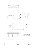
Page 99: ... 8 90 3 60 1 80 17 30 8 65 3 56 1 78 NOTE ALL INSTRUMENTS MAY BE MOUNTED HORIZONTALLY AS SHOWN ABOVE OR VERTICALLY ALL DIMENSIONS ARE IN INCHES Figure 5 7 Relay Dimensions Panel Cutout and Drill Plan 5 10 Installation SEL 267D Instruction Manual Date Code 921207 ...

Page 100: ...Figure 5 8 SEL 267D Horizontal Front and Rear Panel Drawing Date Code 920326 Installation SEL 267D Instruction Manual 5 11 ...

Page 101: ...EL 221F 1 Instruction Manual MAINTENANCE TESTING TABLE OF CONTENTS Initial Checkout 6 l Functional Tests 6 5 Calibration 6 9 Troubleshooting Guide 6 9 Troubleshooting Table 6 9 TABLES Table 6 1 Fault Listings 6 4 Table 6 2 Fault Results 6 4 ...

Page 102: ...ut without referring to the detailed descriptions Inspect the instrument for physical damage such as dents or rattles Connect a computer terminal to PORT 2 on the front or rear panel of the relay The terminal should be configured to 2400 baud eight data bits two stop bits and no parity Be sure your terminal is compatibly configured The FUNCTIONAL DESCRIPTION Section provides additional details con...

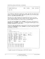
Page 103: ...command allowed at this level is ACCESS which admits you to Access Level 1 as described below Type the command ACCESS and press ENTER At the prompt enter the password OTTER and press ENTER The prompt should appear indicating that you have established communications at Access Level 1 The relay is shipped with demonstration settings which you may inspect using the SHOWSET command Type SHOWSET and pr...

Page 104: ... Connect the dotted C current input terminal to both the A and B current source returns Set the A phase current source to 1 ampere at the same angle as the A phase voltage Set the B phase current source to 1 ampere at the same angle as the B phase voltage Turn the relay power back on execute the ACCESS command and enter the password OTTER again Use the METER command to measure voltages and current...

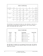
Page 105: ...receding table should cause certain combinations of output relays to remain closed and front panel LEDs to remain illuminated as long as the fault condition persists The following table shows the results Table 6 2 Fault Results Location 9 miles 9 miles 36 miles 36 miles 54 miles 54 miles Type AG BC AG AG AG BC Output Relays TRIP A1 A2 A3 A4 TRIP A1 A2 A4 TRIP A1 A2 A3 A4 TRIP A1 A2 A4 TRIP A1 A2 A...

Page 106: ...ground overcurrent relay element caused the trip ZlDG set to zero or instantaneous trip for the example 69 kV line The displayed targets generally disclose the relay element that caused the trip to occur for the fault The fault targets are automatically cleared by the next fault before the new fault targets are presented Each fault generates a short event report Type EVENT 1 and press ENTER to dis...

Page 107: ...C Apply 50 Vac balanced from the terminals to the test set neutral point 2 Connect the current inputs and apply balanced three phase current of five amperes through the three inputs 3 Use the METER command to inspect the measured voltages currents and power Voltages VA VB and VC should equal the applied voltage times the potential trans former ratio setting With the Example 69 kV Line settings you...

Page 108: ...FP bit to check the positive sequence element Apply the following balanced three phase voltages to the relay MAGNITUDE ANGLE Use an amplitude of 5 amperes for IA and move the phase of IA with respect to the balanced three phase currents Observe the boundary of the positive sequence directional element at MTA 90 VA VB 67 67 0 120 VC 67 volts 120 degrees Overcurrent Element Checking Type TARGET 1 EN...

Page 109: ...dulated IRIG B time code to the Auxiliary Port of the relay with a series resistor to monitor the current Adjust the source to obtain an ON current of about 10 mA 2 Execute the IRIG command and make sure the SEL 267D relay clock displays the correct date and time Note For a convenient inexpensive test of the IRIG B port use a recording of the IRIG B signal passed through a simple demodulator Pleas...

Page 110: ...he power is on but do not turn system off if it is on Measure and record the voltage present at all control inputs Measure and record the state of all output relays Inspect the cabling to the serial communications ports and be sure that a communications device is connected to at least one communications port TROUBLESHOOTING TABLE All Front Panel LED S Dark when TARGET RESET Button is Pushed Power ...

Page 111: ...cabling System is in the XOFF state halting communications type CONTROL Q to put system in XON state Tripping Output Relay Remains Closed Following Fault Tripping condition still present Output relay contacts burned closed Failure of main board No Prompting Message Issued to Terminal upon Power Up Terminal not connected to system Wrong baud rate Improper connection of terminal to system Other port...

Page 112: ...orrectly set Check terminal configuration see COMMANDS AND SERIAL COMMUNICATIONS section Self Test Failure 5 Volts Power supply 5 volt output out of tolerance See STATUS command A D converter failure Self Test Failure 15 Volts Power supply 15 volt output out of tolerance See STATUS command A D converter failure Self Test Failure 15 Volts Power supply 15 volt output out of tolerance See STATUS comm...

Page 113: ... IC replace RAM Self Test Failure A D Converter A D converter failure RAM error not detected by RAM test Stall Relay Closed Alarm Power is off Blown fuse Power supply failure Improper EPROMs or EPROM failure Main board failure 6 12 Maintenance and Testing SEL 267D 167D Instruction Manual Date Code 940208 ...

Page 114: ......

Page 115: ......

Page 116: ...D Instruction Manual APPENDICES TABLE OF CONTENTS Appendix A Firmware Versions in this Manual Appendix A 1 Appendix B Parts Placement Diagram Appendix B 1 Appendix C Onebus Program to Compute Test Set Settings for Testing Distance Relays Appendix C 1 ...

Page 117: ...e Product Firmware Revision 4 167D 267D Main Board Configurations SEL 167D R602 ACB rotation fast meter SEL 167D 3 R401 Base Product fast meter fast operate SEL 167D R404 Base Product fast meter SEL 167D R601 SEL 167D 3 R400 SEL 167D R403 SEL 167D R600 SEL 167D R402 SEL 167D R401 This firmware differs from previous versions as follows The inputs CR and CR LF yield identical outputs Allow fast oper...

Page 118: ...ware using the EVENT command This is an FID number with the Part Revision number in bold FID SEL l67D R403 656m2ps D940830 For a detailed explanation of the Firmware Identification Number FID refer to Section 4 EVENT REPORTING Appendix A 2 Appendix A SEL 267D 167D Instruction Manual Date Code 950829 ...

Page 119: ...APPENDIX B INTERNAL DIAGRAMS SEL 200 Series Main Board Troubleshooting Test Points and Jumper Locations Date Code 931130 Appendix B Appendix B 1 SEL 267D 167D Instruction Manual ...

Page 120: ...s used in the ground fault computations Enter source impedance as a per unit value with a base of the previously entered transmission line data For example if the radial system has a source impedance of about ten percent of the entered line impedance enter 0 1 for the per unit distance from the source to the bus Specify the distance from the bus to the fault as a fraction of the total line length ...

Page 121: ... AI J BR S RI BI S Sl GOSUB 1000 AR RR AI RI BR O BI SQR 3 GOSUB 1000 635 TR RR TS RI 640 UB 67 0 5 TR 650 VB 67 SQR 3 2 TS 660 UC 67 0 5 TR 670 VC 67 0 5 SQR 3 TS 675 FF B C 680 GOSUB 4041 900 INPUT IMP BUS FAULT OR QUIT I B F Q A 910 IF A I THEN GOTO 50 920 IF A B THEN GOTO 75 930 IF A F THEN GOTO 120 ELSE GOTO 999 999 END 1000 REM MULT SUBROUTINE 1010 REM AR AI BR BI RR RI 1020 RR AR BR AI BI 1...

Page 122: ...hows self test status TARGET Shows data and sets target lights as follows TAR 0 Relay Targets TAR 1 RELAY WORD 1 TAR 2 RELAY WORD 2 TAR 3 RELAY WORD 3 TAR 4 RELAY WORD 4 TAR 5 Contact Inputs TAR 6 Contact Outputs TAR R Clears targets and returns to TAR 0 Be sure to return to TAR 0 when done so LEDs display fault targets TIME h m s Shows or sets time TIM 13 32 00 sets clock to 1 32 00 PM This setti...

Page 123: ...f fault Targets The targets indicate the relay elements that caused the trip These targets are the same as the targets displayed on the front panel of the SEL 167D via the TARGET 0 command The targets field indicates any combination of the following P1 Zone 1 phase fault P3 Zone 3 phase fault G1 Zone 3 ground fault P2 Zone 1 ground fault Zone 2 phase fault G3 51P Phase time overcurrent trip G2 Zon...

Reviews: