CALIBRATION
Each SEL Relay is factory calibrated. If you suspect that the relay is out of calibration,
please contact the factory.
TROUBLESHOOTING GUIDE
Inspection Procedure
The following inspection procedure should be completed before the system is disturbed. After
you finish the inspection procedure, proceed to the TROUBLESHOOTING TABLE.
Measure and record control power voltage present at terminals marked + and -.
Check to see that the power is on, but do not turn system off if it is on.
Measure and record the voltage present at all control inputs.
Measure and record the state of all output relays.
Inspect the cabling to the serial communications ports and be sure that a communications
device is connected to at least one communications port.
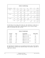
TROUBLESHOOTING TABLE
All Front Panel LED’S Dark when TARGET RESET Button is Pushed
Power is off.
Blown fuse.
Input power not present.
Self test failure.
Target command improperly set.
Note:
For 1, 2, 3, and 4, the ALARM relay contacts should be closed.
Date Code 940208
Maintenance and Testing
SEL-267D/167D Instruction Manual
6-9
Summary of Contents for SEL-167D
Page 3: ......
Page 6: ......
Page 8: ......
Page 9: ......
Page 10: ......
Page 11: ......
Page 51: ...LOGIC DIAGRAMS Date Code 920326 Specifications SEL 267D 167D Instruction Manual 2 31 ...
Page 52: ...Date Code 920326 Specifications 2 32 SEL 267D 167D Instruction Manual ...
Page 53: ...Date Code 920326 Specifications SEL 267D 167D Instruction Manual 2 33 ...
Page 54: ...Date Code 920326 Specifications SEL 267D 167D Instruction Manual 2 34 ...
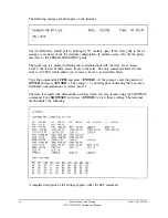
Page 88: ...SAMPLE EVENT REPORT ...
Page 114: ......
Page 115: ......


