


Function Parameters
41 - 140
Function
code
Name
Detailed instruction of parameters
Default
value
Modify
P02.26
Motor overload
protection
selection
0: No protection
1: Common motor
(with low speed compensation). Because the
heat-releasing effect of the common motors will be weakened, the
corresponding electric heat protection will be adjusted properly. The
low speed compensation characteristic mentioned here means
reducing the threshold of the overload protection of the motor whose
running frequency is below 30Hz.
2: Frequency conversion motor
(without low speed
compensation). Because the heat-releasing of the specific motors
won’t be impacted by the rotation speed, it is not necessary to
adjust the protection value during low-speed running.
2
◎
P02.27
Motor overload
protection
coefficient
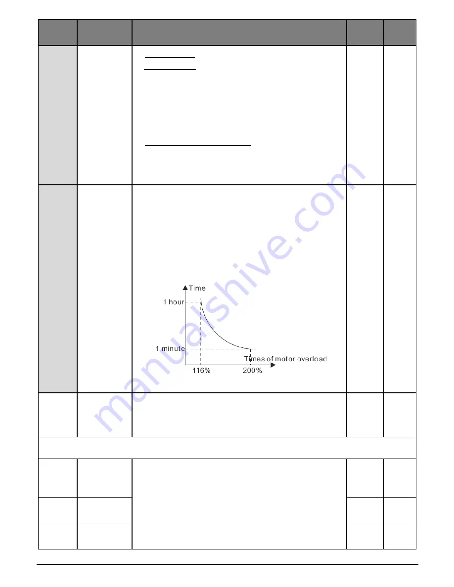
Times of motor overload M = Iout/(In*K)
In is the rated current of the motor, Iout is the output current
of the inverter and K is the motor protection coefficient.
So, the bigger the value of K is, the smaller the value of M is.
When M =116%, the fault will be reported after 1 hour, when
M =200%, the fault will be reported after 1 minute, when
M>=400%, the fault will be reported instantly.
Setting range: 20.0%~120.0%
100.0%
○
P02.28
Correction
coefficient of
motor power
Correct the power displaying of motor. Only impact the displaying
value other than the control performance of the inverter.
Setting range: 0.00~3.00
1.00
○
P03 Group Vector control
P03.00
Speed loop
proportional
gain 1
The parameters P03.00~P03.05 only apply to vector control
mode. Below the switching frequency 1 (P03.02), the speed
loop PI parameters are: P03.00 and P03.01. Above the
switching frequency 2 (P03.05), the speed loop PI
parameters are: P03.03 and P03.04. PI parameters are
gained according to the linear change of two groups of
parameters. It is shown as below:
20.0
○
P03.01
Speed loop
integral time1
0.200s
○
P03.02
Low switching
frequency
5.00Hz
○
Summary of Contents for CV30
Page 1: ...USER MANUAL INVERTER CONTROLVIT CV30...
Page 2: ......
Page 27: ...Keypad Operation Procedure 27 140 Figure 4 5 Sketch map of state watching...
Page 89: ...Function Parameters 89 140 5 2 Diagram of quick start...
Page 139: ......