background image

Galaxy Raid GHDX4 SAS<>SAS/SATA 12Bay


Installation / Hardware Reference Manual


4-4


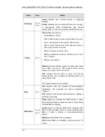
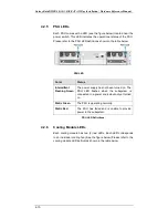
Name 

Color 

Status 

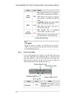
PWR 

(Power) 

Blue 

ON

  indicates that power is supplied to 

the system, and system state is normal. 

OFF

  indicates that no power is supplied 

to the system or the RAID controller has 
failed.


BUSY 

White


FLASHING 

indicates that there is active 

traffic on the host/drive channels. 

OFF 

indicates that there is no activity on 

the host/drive channels.


ATTEN 

(Attention) 

Red 

ON


indicates that a component 

failure/status event has occurred. 

OFF

 indicates that the subsystem and all 

its components are operating correctly.


LCD Panel LED Definitions 


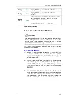
 NOTE:


During the power-on process, the ATTEN LED will light up 
steadily. Once the subsystem successfully boots up with no faults, 
the ATTEN LED will turn off. 


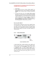
4.2.3 

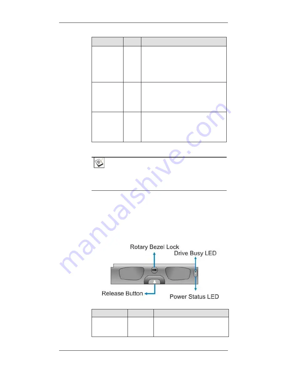
Drive Tray LEDs 

Two (2) LED indicators are located on the right side of each drive 
tray. When notified by a drive failure message, you should check the 
drive tray indicators to find the correct location of the failed drive. 
Replacing the wrong drive can lead to failure of two members of a 
logical array (RAID 3/5) and thus destroy data in it.  


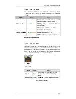
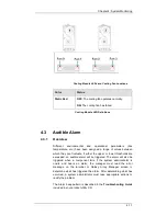
Drive Tray LEDs 

Name 

Color 

Status 

Drive Busy 

Blue


FLASHING

  indicates data is being 

written to or read from the drive. 
The drive is busy. 

Summary of Contents for GX4L-2240R2-12S6

Page 1: ...ide the performance protection and expansion capabilities for diverse customer environments PLEASE READ BEFORE INSTALLATION MODELS GX4L 2240S2 12S6 12 BAY SAS 6G to SAS SATA II RAID Subsystem Single C...

Page 2: ...Contact Information Americas Rorke Data Inc 7626 Golden Triangle Drive Eden Prairie MN 55344 USA Tel 1 800 328 8147 Fax 1 952 829 0988 1 techsupport rorke com http www rorke com...

Page 3: ...entations or warranties with res pect to the contents hereof and specifically disclaims any implied warranties of merchantability or fitness for any particular purpose Furthermore Rorke Data reserves...

Page 4: ...rdous conditions and the consequences of accessing non field serviceable units e g system backplane or power supplies 2 Unplug the system before you move it or when it has become damaged RELIABLE EART...

Page 5: ...g in modules The system should not be operated with the absence of any covers HANDLING PRECAUTIONS 1 The system can either be installed into a standard EIA 310 19 rack cabinet or placed on a desktop M...

Page 6: ...of this equipment in a residential area is likely to cause harmful interference in which case the user will be required to correct the interference at his own expense Any changes or modifications not...

Page 7: ...In Compliance with AeA China RoHS Regulations SJ T 11364 2006 ITE BSMI Class A CNS 13438 for Taiwan This device is in conformity with UL standards for safety FC to SAS SATA 3U 16 4U 24 Bay RAID Subsy...

Page 8: ...y are in compliance with the above regulations Disposal of Old Electrical Electronic Equipment Applicable in the European Union and other European countries with separate collection systems This symbo...

Page 9: ...1 2 6 Power Supply Units 1 9 1 2 7 Cooling Modules 1 10 1 3 SYSTEM MONITORING 1 10 1 3 1 I2C bus 1 10 1 3 2 LED Indicators 1 10 1 3 3 Audible Alarms 1 11 1 4 HOT SWAPPABLE COMPONENTS 1 11 1 4 1 Hot s...

Page 10: ...AUDIBLE ALARM 4 11 4 3 1 Overview 4 11 4 3 2 Alarm Triggers 4 12 4 3 3 I 2 C 4 12 CHAPTER 5 SYSTEM MAINTENANCE 5 1 OVERVIEW 5 1 5 1 1 Maintenance 5 1 5 1 2 General Notes on Component Replacement 5 2...

Page 11: ...k drives separately in the drive trays and in the original package foam blocks If using the original package material other replaceable modules can stay within the enclosure The Galaxy subsystems come...

Page 12: ...er models come with two RAID controllers that should always be present Single controller models come with a single RAID controller and a metal sheet is placed over the lower controller bay at the rear...

Page 13: ...f this manual the Galaxy series is referred to as simply the subsystem or the system and Rorke is sometimes abbreviated as Gal Important Messages Important messages appear where mishandling of compone...

Page 14: ...ry message Lists Bulleted Lists Bulleted lists are statements of non sequential facts They can be read in any order Each statement is preceded by a round black dot Numbered Lists Numbered lists are us...

Page 15: ...Galaxy Raid GHDX4 SAS SAS SATA 12Bay Installation Hardware Reference Manual xiv This page is intentionally left blank...

Page 16: ...AS channel is capable of a 2400MB s bandwidth With a passive backplane redundant hot swappable component design and sophisticated firmware the subsystem is ideal for high availability applications The...

Page 17: ...the front panel are referred to as Front Panel Components and components accessed through the rear panel are referred to as Rear Panel Components 1 1 2 2 Physical Dimensions The Galaxy 12Bay RAID com...

Page 18: ...n keys and a mute button 1 1 2 4 Hard Disk Drive Numbering The front section of the enclosure houses twelve 12 hard drives in a 4x3 configuration When viewed from the front the drive bays slots are nu...

Page 19: ...optional for the single controller Galaxy RAID The CBM consists of a BBU Battery Backup Unit and FBM Flash Backup Module The BBU sustains unfinished writes cached in memory and cached data is distribu...

Page 20: ...A rotary bezel lock prevents accidental removal while a convenient release button ensures fast and efficient drive swapping There are screw holes on the sides of the drive tray for securing hard driv...

Page 21: ...oller Faceplate Mini SAS6G Host Ports The RAID controller features two 2 6Gb s SAS host ports labeled CH0 and CH1 SAS Expansion The SAS Expansion port is meant to connect to JBOD expansion enclosures...

Page 22: ...defaults in cases when upgrading firmware upgrading DIMM size or if an administrator forgets the system password For more details please refer to Chapter 4 1 2 4 Cache Module The controller default f...

Page 23: ...gin to charge its batteries to its full capacity It normally requires approximately twelve 12 hours for the battery to be fully charged If the battery is not fully charged after twelve 12 hours there...

Page 24: ...own in the figure above each PSU comes with a power socket for power cord connection and an on off power switch A single LED indicates the PSU status When a PSU failure occurs the LED is lit constantl...

Page 25: ...different monitoring methods that provide you with continual updates on the status of the system and the individual components The following monitoring features are included 1 3 1 I2C bus The followin...

Page 26: ...ou hear an audible alarm it is imperative that you determine the cause and rectify the problem immediately Event notification messages indicate the completion configuration tasks status of components...

Page 27: ...3 Normalized Airflow Proper cooling is referred to as normalized airflow Normalized airflow ensures the sufficient cooling within the system and is only attained when all components are properly inst...

Page 28: ...nual to prevent difficulties during installation and damage to your subsystem 2 2 Installation Prerequisites 1 Static free installation environment The Galaxy HDX4 12 Bay RAID system must be installed...

Page 29: ...r sources Cable type is determined by the shipped to area 2 One Mini SAS cable 1 2m Other cables are user supplied 1 Mini SAS SFF 8088 to SFF 8088 cables are available for your purchase Please see Cha...

Page 30: ...wish to change the pre installed 1GB DDRII DIMM module you can find DIMM replacement procedures in Chapter 5 8 CBM If you wish to install the optional CBM do it before you power on the subsystem 9 Ra...

Page 31: ...lies to separate power sources e g one to a power outlet and the other to a UPS system 6 Thermal notice All drive trays even if they do not contain a hard drive must be installed into the enclosure Le...

Page 32: ...ce You may also refer to Appendix A of this manual for technical details 11 Airflow considerations The system requires an airflow clearance especially on the front and the rear sides For proper ventil...

Page 33: ...17 Never open the system top cover For safety reasons only qualified service personnel should access the interior of the chassis 18 Always secure every enclosure module by its retaining screws or mak...

Page 34: ...m Discharge the static electricity accumulated in your body by wearing an anti static wristband Use antistatic strap during handling Connect the equipment end of the strap to an unfinished chassis sur...

Page 35: ...are the Unpacking List against the actual package contents to confirm that all required materials have been received Carefully check the items contained in each box before proceeding with installation...

Page 36: ...k Installation Guide 5 A product utility CD containing the Installation and Hardware Reference Manual this document the Operation Manual firmware the Galaxy Array Manager User s Manual and other relat...

Page 37: ...s designed to fit into a variety of 19 inch rack cabinets or racks Make sure you have an appropriate site location and cables prepared with adequate lengths to connect to power source and other device...

Page 38: ...cross head screwdrivers One 1 medium size flat head screwdriver Because the RAID system can weigh 17 kilograms without hard disk drives two 2 people are required to rack mount the enclosure CAUTION Th...

Page 39: ...awing below CAUTION The mounting positions must be carefully measured so that rails can be mounted parallel to each other Step 2 Use the figures below to measure the relative locations of the cage nut...

Page 40: ...inner glides to the sides of chassis using the included screws When attaching the inner glides orient them so that the slimmer part of the glides bends towards the center of chassis If installed in a...

Page 41: ...d of the L shape rail 01 faces inward Loosen the four screws near the end of the L shape bracket to adjust rail length Fasten them when length adjustment is done Adjust the Rail Length Fitting the Rai...

Page 42: ...ts behind the enclosure ears using the four 6 32 x 10mm flat head screws 06 When installing a RAID enclosure use filler plates with an R mark Use those with a J mark for JBODs Securing bezel mounting...

Page 43: ...ides fit into the U shape brackets on the slide runners A click sound will be heard when the inner glides catch the spring latches on the slide runners Step 8 Fasten four screws provided in your enclo...

Page 44: ...you Removing Chassis from Rack Step 4 When the chassis is released slowly pull the chassis from rack Another person should be helping you to remove the chassis from the rack 2 7 Controller Installati...

Page 45: ...Step 5 Fasten the retention screws Once fully inserted secure the controller module to the chassis by fastening the retention screws through the holes underneath the ejection lever Step 6 Continue wi...

Page 46: ...oard on the drives with your tools may cause damage to the drives 2 Observe all ESD prevention methods when installing drives 3 Only use screws supplied with the drive canisters Longer screws can dama...

Page 47: ...n secured within the drive trays the drive trays can be installed into the system WARNING All drive trays must be installed into the enclosure even if they do not contain a hard drive If there are emp...

Page 48: ...se the front bezel Make sure the front bezel is closed properly to ensure that the back end connector is properly mated with the corresponding connector on the backplane If the front bezel can not be...

Page 49: ...for the single controller subsystem If purchased install the CBM on the arrival of your system before installing the RAID controller into the subsystem To install a CBM module Skip steps 1 4 if instal...

Page 50: ...into the canister The orientation is shown in the below figure See 1 in the figure below 5 2 Carefully orient the BBU so that the golden finger connector on the BBU is properly aligned with that on th...

Page 51: ...den fingers are fully inserted Press the SSD down The retention clips on the SSD socket will hold the SSD in place Step 7 Install the RAID controller back into chassis Insert the controller slowly int...

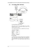
Page 52: ...power off procedures is also given in this chapter 3 1 Host Connection Prerequisites 3 1 1 Host Link Cables One 1 120cm SFF 8088 to SFF 8088 host link cable is included with your purchase You can con...

Page 53: ...siderations When selecting the number of hard drives to be included in a logical configuration the host channel bandwidth and the mechanical performance of individual disk disks should be considered I...

Page 54: ...the same capacity not only in the same logical drive but also in the whole configuration Mixing drives of different sizes and speeds can cause some operation problems Mixing drives in RAID enclosures...

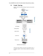
Page 55: ...4 3 2 Sample Topology Sample 1 DAS Direct Attached Storage Connection with redundant host paths Fault tolerant Host Connection Although the Galaxy HDX4 can come with a single RAID controller it is sti...

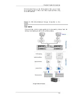
Page 56: ...cal groups of drives Avail these logical partitions using more LUN numbers Sample 2 DAS Direct Attached Storage Connections to Two Servers NOTE If you would like a LUN a logical partition to be access...

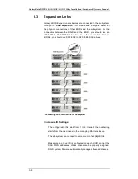
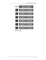
Page 57: ...ould use an SFF 8088 to SFF 8088 SAS cable As to the connection between JBODs you should use SFF 8088 to SFF 8088 SAS cables Connecting SAS JBODs with the Subsystem Enclosure ID Settings The configura...

Page 58: ...Chapter 3 System Connections 3 7 Setting the Enclosure ID...

Page 59: ...or pin swap is required Use a straight through serial cable or a USB to DB9 converter cable The serial port s defaults are Baud rate 38400 Data bit 8 Parity none Stop bit 1 Flow control Hardware Seri...

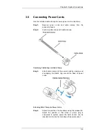
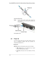
Page 60: ...cable clamps Combining Cable Strap and Cable Clamp Step 3 Attach cable clamps to the power cords by opening and enwrapping the plastic ring around the base of power cords Attaching Cable Clamps to Pow...

Page 61: ...power sockets Attaching Power Cords 3 6 Power On Once all of the disk drives have been properly installed and the I O ports or management interfaces have been connected the subsystem can be powered on...

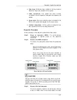
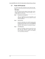
Page 62: ...wer on the expansion enclosures Step 2 Power on the RAID subsystem To power on the subsystem please follow the procedures below Using the included power cords connect both power sockets on the subsyst...

Page 63: ...once the initialization is completed 4 SAS port LEDs The Link LED near the SAS ports should illuminate green indicating successful connection has been established 5 PSU LEDs If the PSU is operating n...

Page 64: ...ssing various interfaces Verifying the installed cache memory System is ready You can now start host LUN mapping by using the system s firmware or GAM software management suite When host LUN mapping h...

Page 65: ...plications to stop all I O accesses to the subsystem Please refer to the documentation that came with your applications Step 2 Flush the cache Locate the C_Dirty LED on the controller module to check...

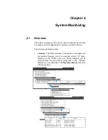
Page 66: ...ion statuses The monitoring features include Firmware The RAID controller in the system is managed by a pre installed firmware which is accessed using a PC hyper terminal via the COM1 serial port Devi...

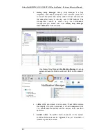
Page 67: ...0BaseT management port Please refer to the Galaxy Array Manager User s Manual for further details Use Galaxy Array Manager s Notification Manager to set up automated event notification via Email MSN L...

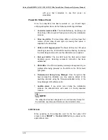
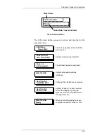
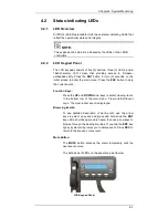
Page 68: ...Press the ESC button to skip the current event Function Keys Press the UP and DOWN arrow keys to select viewing items In the bottom row of the main menu View and Edit Event Logs the most recent event...

Page 69: ...es that the subsystem and all its components are operating correctly LCD Panel LED Definitions NOTE During the power on process the ATTEN LED will light up steadily Once the subsystem successfully boo...

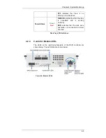
Page 70: ...tes that the drive bay is populated and is working normally RED indicates that the disk drive has failed or a connection problem occurred Drive Tray LED Definitions 4 2 4 Controller Module LEDs The LE...

Page 71: ...king indicates that the system is writing cached data from cache memory to flash backup during power outage Once done LED is turned off OFF indicates that the cache is clean and that the battery backu...

Page 72: ...d There is a non latch type push button accessed through an opening on the controller faceplate Why restoring defaults 1 Some of the latest firmware updates may be incompatible with the firmware curre...

Page 73: ...es functions Configurations such as ID LUN mapping will be restored after a system reset How to use the button After the system is powered down you can use a straighten paper clip to press the button...

Page 74: ...s link Amber indicates a 3Gb s link OFF indicates an incongruous link status SAS Host Port LED Definitions 4 2 4 3 LAN Port LEDs A shielded Ethernet cable is recommended for connecting the RJ 45 Ethe...

Page 75: ...Intermittent Flashing Green The power supply has not been turned on The PSU LED flashes when the subsystem is connected to a power source but not yet turned on Static Green The PSU is operating normal...

Page 76: ...ey can fluctuate If either the upper or lower thresholds are exceeded an audible alarm will be triggered The alarm will also be triggered when a component fails If the system administrator is onsite a...

Page 77: ...e may occur 4 3 2 Alarm Triggers If any of the following components fails the audible alarm will be triggered RAID controller Cooling module PSU CBM Hard disk drives Sensors and presence detection cir...

Page 78: ...have acquired a system serial number from system EEPROM and could have used the serial number to generate a unique controller ID As the result you may encounter SAN problems with identical port names...

Page 79: ...omponent caution should be taken to ensure that the components are handled in an appropriate manner Rough or improper handling of components can lead to irreparable damage When removing a RAID control...

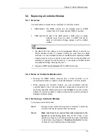
Page 80: ...occur 2 Replace a DIMM one 1 minute after the BBU is removed 5 2 2 Notes on Controller Maintenance Re using the DIMM module removed from a failed controller is not recommended unless you have a simil...

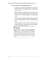
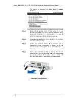
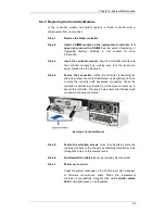
Page 81: ...the power cords Step 4 Disconnect all cables that are connected to the controller module you wish to replace Step 5 Loosen the retention screws from controller Use a medium size Phillips screwdriver t...

Page 82: ...reaching the end and you feel the contact resistance use slightly more force to mate the controller with backplane connectors When the controller is almost fully inserted pull the ejection levers up...

Page 83: ...tions stipulated above are strictly adhered to 5 3 2 Selecting the Memory Modules Compatibility To avoid compatibility issues it is recommended to contact your system vendor for a compatible module We...

Page 84: ...procedures Step 7 Reinstall the controller module After the DIMM module has been properly installed install the RAID controller 5 4 Replacing a Faulty CBM The CBM module can sustain and transfer cach...

Page 85: ...se will void your warranty Always dispose of a replaced battery in an ecologically responsible manner Dispose of used BBUs at authorized battery disposal sites only Do not place a BBU near a heat sour...

Page 86: ...it towards the charger board See 1 in the figure below Installing BBU into a Controller Step 4 Carefully align the BBU connector with that on the charger board Put the BBU down to mate the connectors...

Page 87: ...controller and return the controller through standard RMA procedure 5 4 4 Replacing a Faulty Flash Backup Module To replace a flash backup module please follow these steps Step 1 Remove controller as...

Page 88: ...a replacement is readily available Removing a PSU without a replacement will cause severe disruptions to the internal airflow and the system will overheat possibly causing irreparable damage to some o...

Page 89: ...s removed form the chassis the cooling module is also removed from the chassis Hence the airflow provided by the cooling module is also disabled With an empty module bay airflow will also be disrupted...

Page 90: ...two 2 within each cooling module These cooling modules control the internal operating temperature and therefore their working integrity should be maintained at all times Detecting a failed cooling mo...

Page 91: ...If the process takes too long the accumulated heat can damage the system Step 1 Snatch the retention latches towards the center and then pull the cooling module out of the chassis Removing a Cooling...

Page 92: ...from the system after the front bezel has been opened can cause data errors Slow and careful removal When removing a drive tray from the system pull the drive tray out only about one inch and then wa...

Page 93: ...1 Remove the front bezel if installed and identify the location of the drive tray that contains a hard drive indicated as faulty You may use firmware utility or Galaxy Array Manager software to locat...

Page 94: ...Tray Front Bezel Step 4 Remove the drive tray by pulling it one inch away from the drive bay Wait for at least 30 seconds for the disk drive to spin down and then gently and carefully withdraw the dr...

Page 95: ...with a drive bay Gently slide it in until the drive tray reach the end of drive bay This should be done smoothly and gently Installing a Drive Tray Step 10 Close the front bezel Make sure the front be...

Page 96: ...with fault tolerance e g RAID levels 1 3 5 or 6 a logical drive rebuild process will automatically begin You should then verify the beginning of the rebuild process using Galaxy Array Manager or a ter...

Page 97: ...Galaxy Raid GHDX4 SAS SAS SATA 12Bay Installation Hardware Reference Manual 5 20 This page is intentionally left blank...

Page 98: ...ied Non operating 40 to 60 C Altitude Operating Sea level to 3660m 12 000 ft Non operating Sea level to 12 192m 40 000 ft Power Requirements Input Voltage 100VAC 6A to 240VAC 3A with PFC auto switchin...

Page 99: ...3 BSMI CNS 13438 FCC FCC Part 15 subpart B Certificates IEC 60068 2 MIL STD 810E 883E ISTA ASTM D3332 IPC TM 650 IEC 61000 4 2 1995 A2 2000 IEC 61000 4 3 1995 A2 2006 IEC 61000 4 4 2004 IEC 61000 4 5...

Page 100: ...orts Host Interface Multiple SAS PHYs logically combined into 2 host channels Host Channels Multiple SAS PHYs logically combined into 2 host channels Drive Interface 12 drive bays for 6Gb s SAS or 3Gb...

Page 101: ...es with time record and task scheduling A 3 Power Supply Specifications Specification Nominal Power 350W with active PFC DC Output 12 0V 25A Max 5 0V 25A Max 3 3V 20A Max Input Frequency 47 to 63Hz AC...

Page 102: ...on disks for logical drive assemblies to exist after controller replacement basic settings e g channel mode settings are stored on NVRAM Applies to uses such as Drive Roaming Failure Indicator Via au...

Page 103: ...ual A 6 Manual Clone of Suspected Failed Drive Yes Concurrent Rebuild on Multiple Drives in a RAID 0 1 or RAID6 Logical Drive Yes Event triggered operation Firmware applies conservative write through...

Page 104: ...pecification Mini SAS SFF 8088 Connector Pin Description Pin Description A1 GND B1 GND A2 RX0 B2 TX0 A3 RX0 B3 TX0 A4 GND B4 GND A5 RX1 B5 TX1 A6 RX1 B6 TX1 A7 GND B7 GND A8 RX2 B8 TX2 A9 RX2 B9 TX2 A...

Page 105: ...ble The COM 1 Cable is used to connect a PC running terminal emulation program COM1 Serial Port Cable Pinouts P2 P3 Pin Number Pin Name 1 GND 2 TXD 3 RXD P1 Pin Number Pin Name 1 NC 2 RXD 3 GND 4 DTR...

Page 106: ...uts B 3 B 3 Ethernet Port Pinouts Ethernet Port Pinouts Pin Pin Name Pin Pin Name 1 LAN_TXP 5 N2 2 LAN_TXN 6 LAN_RXN 3 LAN_RXP 7 N1 4 N2 8 N1 Ethernet Port Pinout Definitions B 4 Power Connectors IEC...

Page 107: ...Galaxy Raid GHDX4 SAS SAS SATA 12Bay Installation Hardware Reference Manual B 4 This page is intentionally left blank...

Page 108: ...www rorke com Rorke Data An Avnet Company 7626 Golden Triangle Drive Eden Prairie MN 55344 USA Toll Free 1 800 328 8147 Phone 1 952 829 0300 Fax 1 952 829 0988...

Reviews: