Chapter 2: Hardware Installation
2-23
Press Down on the Ejection Levers
Step 4.
Place controller on a clean, static-free surface. Hold
the controller by its metal canister. Never touch the
circuit board or connector pins.
Step 5.
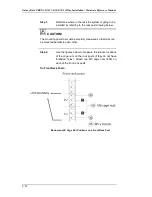
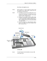
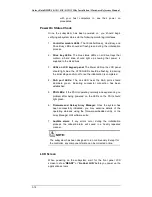
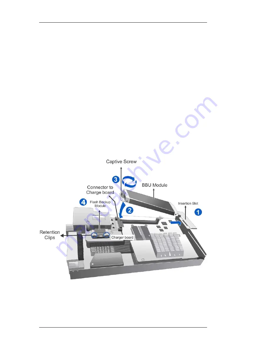
5-1. Install BBU by orienting its protruding edge on one
end into the insertion slot, and lowering it into the
canister. The orientation is shown in the below
figure. See
#1
in the figure below.
5-2. Carefully orient the BBU so that the golden finger
connector on the BBU is properly aligned with that
on the charger board. There are guide pins on
BBU to help properly align the connectors. See
#2
in the figure below.
5-3. Once the connectors are mated, fasten the captive
screw on the BBU to secure the installation. See
#3
in the figure below.
Installing CBM
Step 6.
The flash backup module installation is shown in
#4
in the figure above.

