Chapter 1: Introduction
1-5
1.2 System Components
The subsystem houses many active components and most of them
can be accessed either through the front or the rear panel. The
modular design of these components facilitates their easy installation
and removal. Hot-swap mechanisms are incorporated to eliminate
power surges and signal glitches that might occur when you remove
or installing these modules. Each component is further described
below:
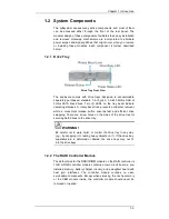
1.2.1 Drive Tray
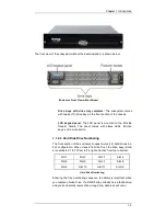
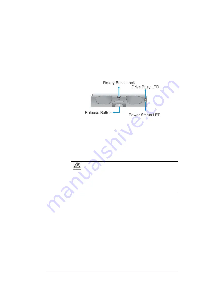
Drive Tray Front View
The enclosure comes with drive trays designed to accommodate
separately purchased, standard 1-inch pitch, 3.5-inch 6Gb/s SAS or
3Gb/s SATA disk drives. Two (2) LEDs on the tray bezel indicate
operating statuses. A rotary bezel lock prevents accidental removal,
while a convenient release button ensures fast and efficient drive
swapping. There are screw holes on the sides of the drive tray for
securing hard drives to the drive tray.
WARNING!
Be careful not to warp, twist, or contort the drive tray in any way
(e.g., by dropping it or resting heavy objects on it). If the drive bay
superstructure is deformed or altered, the drive trays may not fit
into the drive bays.
1.2.2 The RAID Controller Module
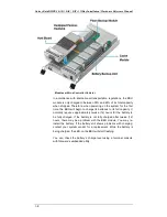
The default size for the DDRII DIMM module on the RAID controller is
1GB. A RAID controller module contains a main circuit board, a pre-
installed memory, battery charger circuitry, and a daughter board with
host port interfaces. The controller module contains no user-
serviceable components. Except when servicing the cache memory
or the CBM module inside, the controller module should never be
removed or opened.

