


Measurement Basics
R&S
®
FSW-K40
28
User Manual 1173.9286.02 ─ 15
Unverified signals
The R&S
FSW tries to start the measurement as soon as you enter the phase noise
application. If it cannot verify a signal, it will try to start the measurement over and over.
To stop the repeated (and probably unsuccessful) signal verification, stop the mea-
surement on the first verification failure.
The available (nominal) frequency range depends on the hardware you are using. For
more information see the datasheet of the R&S
FSW.
If you are not sure about the nominal frequency, define a tolerance range to verify the
frequency. For measurements on unstable or drifting DUTs, use the frequency tracking
functionality.
Frequency verification
When you are using frequency verification, the application intiates a measurement that
verifies that the frequency of the DUT is within a certain range of the nominal fre-
quency. This measurement takes place before the actual phase noise measurement.
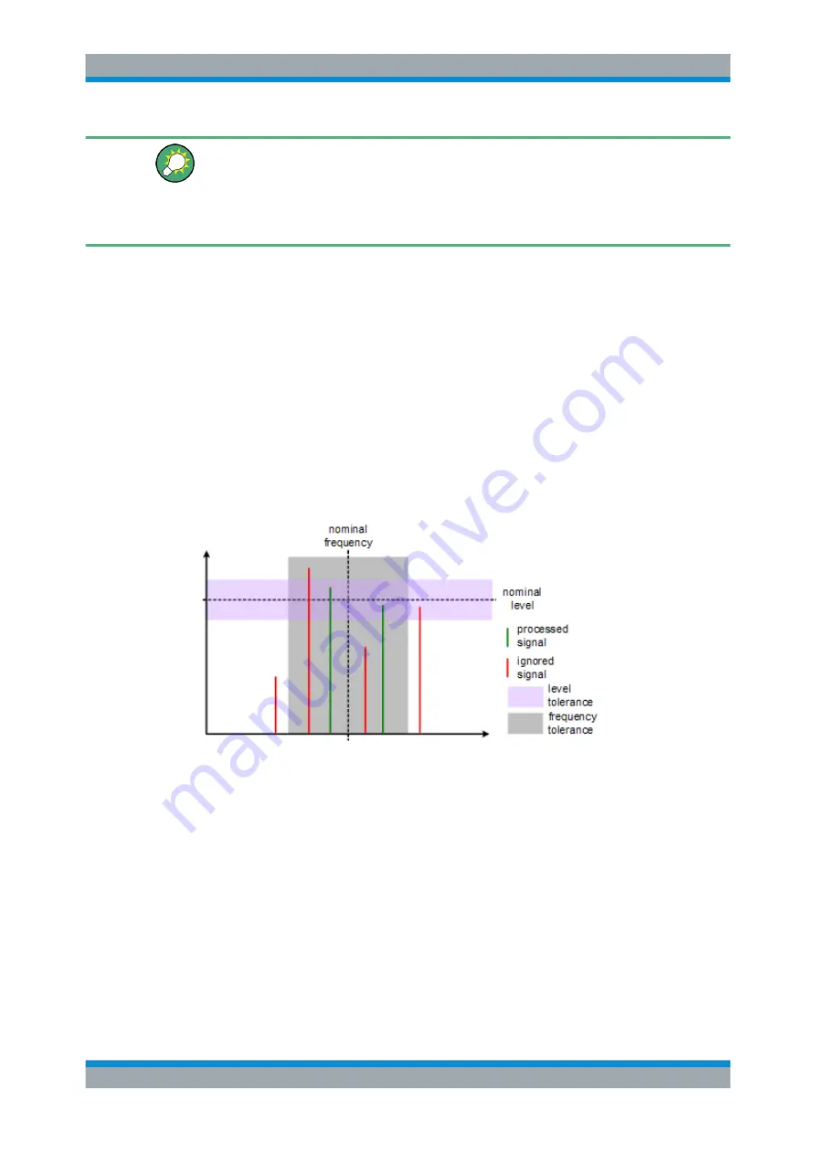
Its purpose is to find strong signals within a frequency tolerance range and, if success-
ful, to adjust the nominal frequency and lock onto that new frequency. The frequency
tolerance is variable. You can define it in absolute or relative terms.
Figure 4-5: Frequency and level tolerance
You can define both absolute and relative tolerances. In that case, the application uses
the higher tolerance to determine the frequency.
If there is no signal within the tolerance range, the application aborts the phase noise
measurement.
In the numerical results, the application always shows the frequency the measurement
was actually performed on. If the measured frequency is not the same as the nominal
frequency, the numerical results also show the deviation from the nominal frequency.
Frequency Determination


