


Wrist Camera - Instruction Manual
Fig. 4-77: This MoveL node was inserted using the Auto Pick button.
Tip
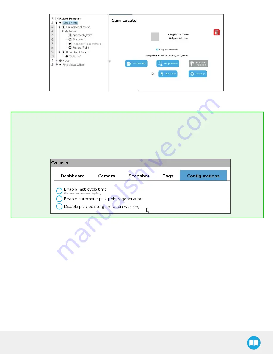
For a smoother experience using Auto Pick, modify teach pendant options under Installation > URCaps > Camera
> Configurations. Check the following radio buttons:
l
" Enable automatic pick points generation"
l
" Disable pick points generation warning"


