2.Installation
14
Printer model:
SP menu > @Remote > Remote Service > Function Flag
MF model:
SP menu > @Remote > Remote Service > Function Flag
Execute the @Remote Settings
1.
Enter the SP mode.
2.
Check if the @Remote status is "0".
Printer model:
SP menu > @Remote > Remote Service > Instl:Condition
MF model:
SP menu > @Remote > Remote Service > Regist Status
If the @Remote status is not "0", ask the @Remote Center Administrator.
3.
Check that the device ID2 has been programmed correctly.
Printer model:
@Remote > Machine No. Setting > ID2 Code Display
MF model:
@Remote > Machine No. Setting > ID2 Code Display
•
6 spaces must be put between the 3-digit prefix and the following 8-digit number (e.g.
xxx______xxxxxxxx).
•
ID2 and the serial number must be the same (e.g. ID2: A01______23456789 = serial No.
A0123456789)
The procedure for checking the serial number is as follows;
Printer model:
SP menu > Engine Maintenance > Serial No.
MF model:
SP menu > Engine SN SP > Serial No.
4.
Input the request number which you have obtained from the @Remote Center GUI, and then enter
OK.
Printer model:
@Remote > Remote Service > Instl:ID #
MF model:
@Remote > Remote Service > Letter Number
5.
Confirm the Request Number.
Printer model:
@Remote > Remote Service > Instl:Reference
MF model:
@Remote > Remote Service > Confirm Execute
6.
Check the confirmation result.
Printer model:
@Remote > Remote Service > Instl:Reference
MF model:
@Remote > Remote Service > Confirm Result
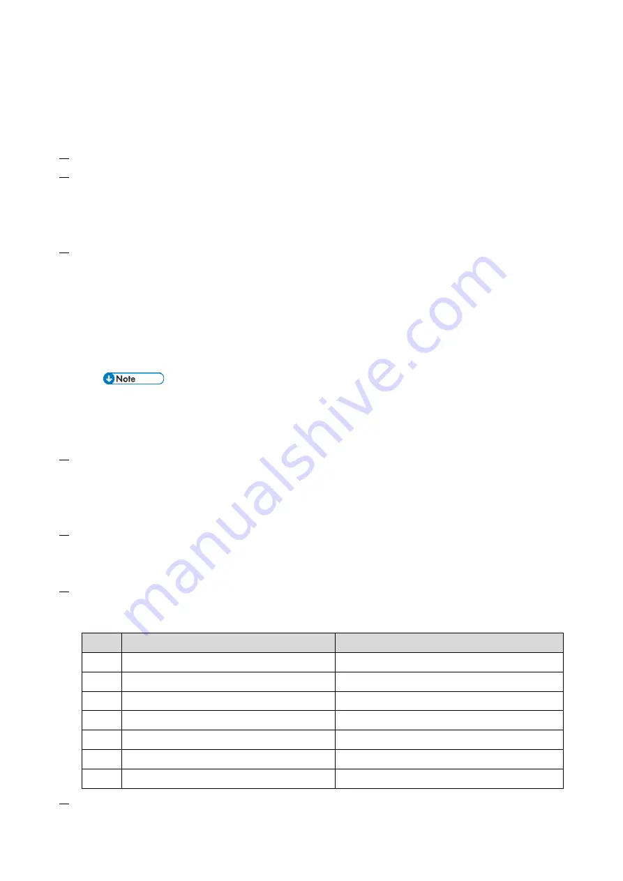
Value
Meaning
Solution/ Workaround
0
Succeeded
-
1
Request number error
Check the request number again.
3
Communication error (proxy enabled)
Check the network condition.
4
Communication error (proxy disabled)
Check the network condition.
5
Proxy error (authentication error)
Check the proxy user name and password.
8
Other error
See "Error Codes" below this.
9
Request number confirmation executing
Processing… Please wait.
7.
Make sure that the screen displays the Location Information only when it has been input at the
Summary of Contents for M C250FW
Page 2: ......
Page 8: ......
Page 12: ......
Page 34: ...3 Preventive Maintenance 22 to remove any remaining moisture ...
Page 45: ...4 Replacement and Adjustment 33 6 Release the belt A and then remove the front cover unit B ...
Page 103: ...4 Replacement and Adjustment 91 MF model 11 Remove the fusing transport drive unit A ...
Page 112: ...4 Replacement and Adjustment 100 MF model 8 Remove the belt cover A ...
Page 183: ...5 System Maintenance 171 8 Press OK on the screen or press on the number keys to exit ...
Page 188: ...5 System Maintenance 176 Special Sender List Configuration Page Printer model ...
Page 189: ...5 System Maintenance 177 MF model ...
Page 260: ...6 Troubleshooting 248 Flowchart ...
Page 271: ...7 Detailed Descriptions 259 ...
Page 297: ...7 Detailed Descriptions 285 Boards Block Diagram Printer Model ...
Page 301: ......


