R01UH0092EJ0110 Rev.1.10
Page 343 of 807
Jul 31, 2012
M16C/64C Group
19. Three-Phase Motor Control Timer Function
19.3
Operations
19.3.1
Common Operations in Multiple Modes
19.3.1.1
Carrier Wave Cycle Control
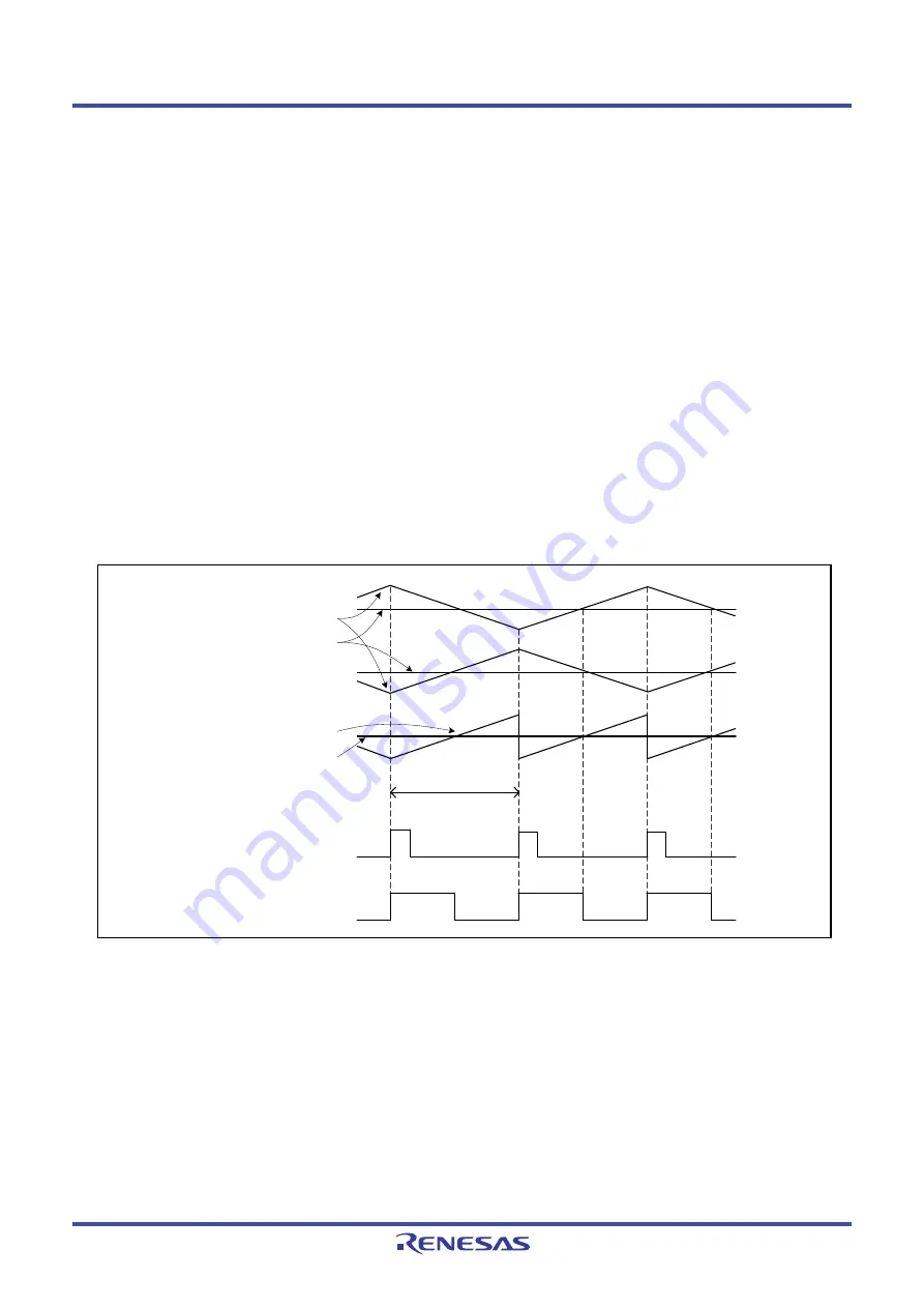
Timer B2 controls the cycle of the carrier wave. In triangular wave modulation mode, the cycle of the
carrier wave is double the cycle of timer B2 underflow. In sawtooth wave modulation mode, the cycle
of the carrier wave is equal to the cycle of timer B2 underflow. Figure 19.3 shows the Relationship
between the Carrier Wave Cycle and Timer B2.
Timer B2 underflow is a start trigger for timers A1, A2, and A4, which control the three-phase PWM
waveform. However, when the INV10 bit in the INVC1 register is 1, writing to the TB2 register while
timer B2 is stopped also generates a trigger for timers A1, A2, and A4.
The frequency of timer B2 interrupt requests can be selected for three-phase motor control timers.
In triangular wave modulation three-phase mode 0 and sawtooth wave modulation mode, when the
setting value in the ICTB2 register is n, a timer B2 interrupt request is generated every nth count of
timer B2 underflow.
In triangular wave modulation three-phase mode 1, when the setting value in the ICTB2 register is n,
a timer B2 interrupt request is generated every nth time of the timing selected by bits INV01 to INV00
in the INVC0 register. However, when bits INV01 to INV00 are 11b, the first interrupt is generated at
the n-1 time of timer B2 underflow.
Figure 19.3
Relationship between the Carrier Wave Cycle and Timer B2
Carrier wave
Cycle of timer B2
Signal wave
Image of Triangular wave
Image of Sawtooth wave
Carrier wave
Signal wave
Timer B2 underflow signal
Timer A1, A2, or A4
one-shot pulse
Summary of Contents for M16C Series
Page 846: ...M16C 64C Group R01UH0092EJ0110...


