background image

Regio Midi manual 

Chapter 7 

  Control modes 

39  

Minimum limit on analogue 0…10 V actuators 

The  minimum  limitation  on  the  analogue  output  is  only  active  in  Bypass,  Occupied  and 
Standby. If the operating mode is Unoccupied or Off, the damper will be closed (0 V on the 
analogue output). See table below: 


Operating mode 

Min. limit 

VAV output (Y2) 

Bypass 

20 % 

2 V 

Occupied 

20 % 

2 V 

Standby 

20 % 

2 V 

Unoccupied 

20 % 

0 V 

Off 

20 % 

0 V 


Many damper actuators have a working range of 2...10 V. This means that to set a minimum 
limitation of 20 %, the min. limitation in the Regio will have to be set to 36 % . 


Forced ventilation depending on the heating/cooling 
output 

At  100  %  heating  or  cooling  output,  forced  ventilation  can  be  activated.  The  function  is 
intended to be used when the heater or cooler is located in the ventilation duct and the system 
is  struggling  to  reach  the  setpoint.  When  the  cooling  or  heating  output  reaches  100  %,  the 
controller will switch to control mode Bypass. 

The controller will remain in forced ventilation throughout the set Bypass time (FS=2h). 

Three different alternatives can be selected for setting the function forced ventilation: 


Not active (FS) 


Forced ventilation at 100% heating or cooling output 


Forced ventilation at 100% cooling output 


Summary of Contents for Regio Midi

Page 1: ...MANUAL REGIO MIDI WE TAKE BUILDING AUTOMATION PERSONALLY Copyright AB Regin Sweden 2017...

Page 2: ...this document is supplied under license by Regin and may be used or copied only in accordance with the terms of the license No part of this document may be reproduced or transmitted in any form in any...

Page 3: ...5 Measurement and testing during installation 17 Wiring for basic models with 3 universal outputs RC C3H RC C3 RC C3O 18 Wiring for model for CO2 control RC C3DOC 21 Wiring for model with built in CO2...

Page 4: ...R 15 MEMORY FUNCTION ON POWER FAILURE 66 CHAPTER 16 MODBUS SIGNAL TYPES 67 CHAPTER 17 MODBUS SIGNALS 69 DISCRETE INPUTS 69 COIL STATUS REGISTER 70 INPUT REGISTER 71 HOLDING REGISTER 72 CHAPTER 18 BACN...

Page 5: ...Regio tool Manual Manual of how to configure the controllers The information is available for download from Regin s website www regincontrols com The document Regio in EXO Projects containing informat...

Page 6: ...naging the functions in one room to large integrated systems with a comprehensive SCADA system Applications The Regio controllers have a discrete design and are easy to use They are suitable in buildi...

Page 7: ...o tool for more information BACnet is only available in models with display Control modes The controllers can be configured for different control modes control sequences Heating Heating or cooling via...

Page 8: ...nd three digital outputs for control of a three speed fan fan coil etc RC C3DFOC has EC fan control on analogue output UO3 H models Models with hidden setpoint O models Models with occupancy button T...

Page 9: ...Regio Midi manual Chapter 3 Models 9 Design RC C3H RC CTH RC C3 RC CT RC C3O RC CTO RC CDTO RC C3DOC RCC C3DOCS RC CF RC CFO RC CDFO RC C3DFOC...

Page 10: ...ACnet only Functions as Modbus RTU Slave BACnet MS TP Modbus 8 bits 1 or 2 stop bits Odd even FS or no parity Galvanically isolated port No BACnet is only available in models with display Memory Non v...

Page 11: ...or KG A 1 DI Closing potential free contact connected to C in one end Outputs DO 24 V AC max 0 5 A UO DO 24 V AC max 2 0 A or AO 0 10 V DC max 5 mA C power output for DI only 24 V DC max 10mA short ci...

Page 12: ...mber of terminals depends on the Regio model Figure 1 Old terminal type 1 3 mm pins Figure 2 Current terminal type 1 1 mm pins Using labels On the back of the electronics cassette there is a set of la...

Page 13: ...ation using Regio tool 1 Download Regio tool to your computer from www regincontrols com 2 Connect the computer to the back of the Regio cassette with an E cable USB or equivalent The E cable USB is c...

Page 14: ...is the pre set operating mode SW3 OFF FS If you want the pre set operating mode to be Stand by set SW3 in mode ON For more information see the chapter Operating modes SW4 8 Follow the tables in the ch...

Page 15: ...e 5 Figure 6 The bottom plate with terminals has several fixing hole combinations Select suitable holes and screw the bottom plate onto the wall or connection box so that the arrows on the bottom plat...

Page 16: ...er is required See figure 7 Figure 7 The figure below shows the location of the terminals The connection diagrams and tables on the following pages show the wiring for basic models the model for CO2 c...

Page 17: ...utputs of a Regio room controller during installation Regin s RC TEST service adapter may be used Simply align the pins at the bottom of the RC TEST with the terminals contained in the controller s so...

Page 18: ...minal 10 G 21 G0 0 V common for UO Internally connected to terminal 11 G0 22 UO3 For VAV control alternatively For forced ventilation 24 V AC output max 2 0 A 24 V actuator is connected between termin...

Page 19: ...or UO1 can be set to NC normally closed or NO normally open 24 UO2 Control output heating or cooling FS For a 0 10 V DC valve actuator max 5 mA FS The valve actuator s 0 10 V control signal terminal i...

Page 20: ...ent SW4 DI window contact Closed contact indicates closed window CI Regin s condensation sensor KG A 1 FS Function terminal 33 DI2 CI SW5 Digital output for 24 V AC thermal actuator Analogue output fo...

Page 21: ...V common for UO Internally connected to terminal 11 G0 22 UO3 Output for VAV or EC fan For forced ventilation 24 V AC output max 2 0 A 24 V actuator is connected between terminal 22 and terminal 20 GD...

Page 22: ...ed between terminals 24 and 20 GDO alternatively For a 24V AC actuator with spring return max 2 0 A The actuator is connected between terminals 24 and 20 This can be configured either through the disp...

Page 23: ...y terminals to terminals 10 and 11 Make sure that the reference pole G0 is connected to the correct terminal on the actuator alternatively Lighting control On Off 23 UO1 Control output heating FS cool...

Page 24: ...ween terminals 30 and 41 AGnd 31 AI2 For a 0 10 V CO2 sensor alternatively Flow input alternatively 0 10 V input 32 DI1 Occupancy detector A potential free contact is connected between terminals 32 an...

Page 25: ...heating or cooling via change over For a 0 10 V DC valve actuator max 5 mA FS The valve actuator s 0 10 V control signal terminal is connected to terminal 23 and its supply terminals to terminals 10...

Page 26: ...etween terminals 30 and 41 AGnd 31 AI2 For a 0 10 V CO2 sensor alternatively Flow input alternatively 0 10 V input 32 DI1 Occupancy detector A potential free contact is connected between terminals 32...

Page 27: ...and terminal 20 GDO 13 DO2 For fan control medium speed 24 V AC output max 0 5 A A 24 V AC relay is connected between terminal 13 and terminal 20 GDO 14 DO3 For fan control high speed 24 V AC output m...

Page 28: ...C normally closed or NO normally open 24 UO2 Control of heating cooling FS or heating cooling via change over For a 0 10 V DC valve actuator max 5 mA FS The valve actuator s 0 10 V control signal term...

Page 29: ...ow contact Closed contact indicates closed window CI Regin s condensation sensor KG A 1 FS Function terminal 33 DI2 CI SW5 Digital output for 24 V AC thermal actuator Analogue output for 0 10 V DC val...

Page 30: ...nt actuator heating decrease 24 V AC output max 0 5 A The actuator s terminal for closing signal is connected to terminal 14 20 GDO 24 V AC out common for DO Internally connected to terminal 10 G 21 G...

Page 31: ...ween terminals 33 and 40 C See Table 1 SW4 40 C 24 V DC out common for DI and UI with digital function 41 AGnd Analogue ground reference for AI and UI with analogue function 42 A RS485 communication A...

Page 32: ...AV only available in C3 models except C3DFOC Heating Cooling Heating Heating or Cooling via change over only available in fan models Heating Cooling Change over with VAV function Heating or cooling Co...

Page 33: ...between the heating setpoint and the cooling setpoint When the room temperature exceeds this limit the controller becomes a cooling controller There is a hysteresis of 0 1 C when the controller chang...

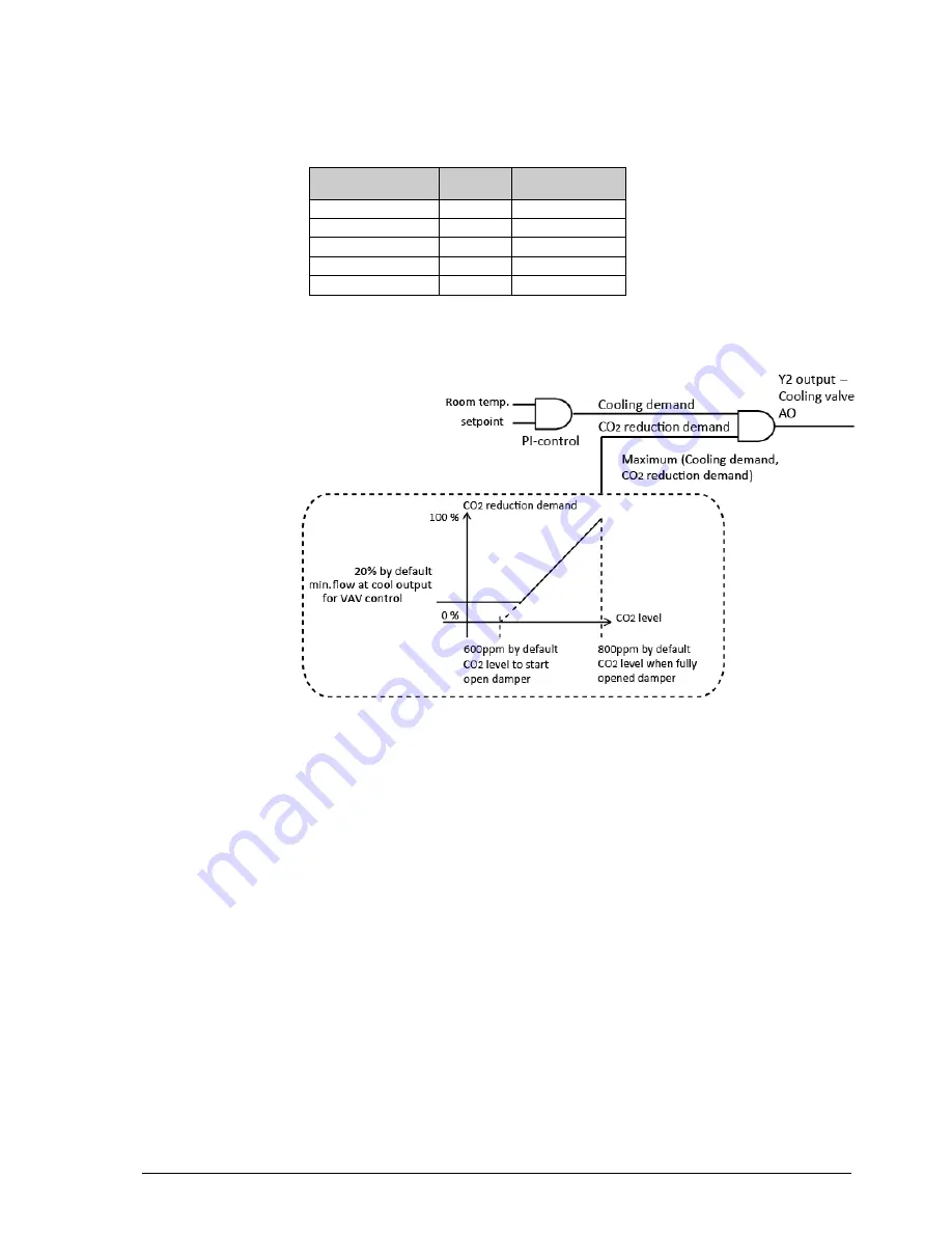
Page 34: ...demand The factory setting is zero which means that the function to open the damper on heating demand is not active The basic flow can also be set separately For VAV control several basic flows exist...

Page 35: ...OC see figure below To avoid Y2 and Y3 opening and closing frequently during switch over a saddle point is implemented Y2 will output 0 10 V linear when the controller output is 0 48 and Y3 will outpu...

Page 36: ...d Y3 i e to open Y3 before Y2 This function is a configuration of the control mode Heating Cooling VAV When the function is active the sequence of Y2 and Y3 will be reversed i e Y3 will open 0 100 whe...

Page 37: ...UO1 UO2 is changed along with the limits for fan start The change over function will be used to switch between summer and winter mode UO2 will be used as a cooling actuator in summer mode and as a hea...

Page 38: ...settable range is 10 50 C The default setting is Control mode Min limitation Max limitation Heating 24 C 35 C Cooling 12 C 24 C A room controller will then work together with a supply air temperature...

Page 39: ...e min limitation in the Regio will have to be set to 36 Forced ventilation depending on the heating cooling output At 100 heating or cooling output forced ventilation can be activated The function is...

Page 40: ...ation drops below this value the controller will remain in presence mode for the duration of the configured occupancy off delay FS 10min Minimum limit for the heating output In some applications it is...

Page 41: ...a read out for the signal To configure this option parameter 81 is set to option 7 0 10 V Flow input AI2 may be configured as a flow calculation input A flow corresponding to 0 V and one corresponding...

Page 42: ...ture interval with configurable min max temperatures FS min 15 C max 30 C For controllers with display the background lighting is not lit but the current room temperature or setpoint depending on the...

Page 43: ...FS 2 hours in Bypass the controller automatically returns to the pre set operating mode Bypass is normally activated when the Occupancy button is pressed via an occupancy detector a central command or...

Page 44: ...Occupied When the Occupancy button is held depressed for more than 5 seconds the controller will change its operating mode to Shutdown Off Unoccupied regardless of the present operating mode Via the...

Page 45: ...controller changes operating mode to Bypass or Occupied If you want to be able to enter the room temporarily without activating Presence to for example pick something up it is possible to configure a...

Page 46: ...r will change to Stand by regardless of what has been set in the central control RegioRemoteState When the controller is in Bypass and the Bypass time has run out the controller will change to the ope...

Page 47: ...trol mode and the current setpoint offset Off In operating mode Off or on open window the controller is a heating controller and controls according to the frost protection setpoint FS 8 C regardless o...

Page 48: ...and the added adjustment is 1 5 C This means that the value 23 5 C will be shown in the display HEAT or COOL will flash depending on which of the setpoint values is the control setpoint when you enter...

Page 49: ...on and off output times on the output The period time is FS 60s The controller varies the on and off output times proportionally depending on the output signal demand to the actuator 3 point actuators...

Page 50: ...resis before opening the actuator The actuator will then remain open until the temperature has reached the setpoint In cooling mode the opposite will occur Actuator exercise All actuators are exercise...

Page 51: ...Manual setting of speed I III means that the speed of the fan in operating modes Stand by Occupied and Bypass is always the set speed In the other operating modes the fan is demand controlled Auto co...

Page 52: ...C3H C3O C3DOC and C3DFOC offer an added function for the control of EC fans When this function is active Y3 will follow Y1 and Y2 respectively As for F models with fan control it is possible to selec...

Page 53: ...ignal it should not be possible to alter the fan speed manually Please note that if the fan configuration is set to not follow the cooling or heating signal and this function is simultaneously active...

Page 54: ...then decrease to the speed set by the extra controller for the remainder of the time set for the boost function The boost function has a higher priority than the manually set fan speed Fan kickstart...

Page 55: ...In simple mode the change over state is set to cooling when the change over temperature goes below the low limit It is set to heating when the change over temperature exceeds the high limit Change ove...

Page 56: ...low room temperature alarm High low temperature alarm is a function to indicate if the room temperature is too high or too low The high room temperature alarm will trigger when the room temperature ex...

Page 57: ...lay the occupancy button has the following indications Occupied Fixed green indication Standby Flashing green indication Bypass Fixed green indication with a short flash Off and Unoccupied No indicati...

Page 58: ...an asterisk are only available on F models Figure 20 Indications in the display INCREASE button Occupancy button DECREASE button AUTO MAN Auto Man indication on the fan Occupancy indication Open windo...

Page 59: ...ute or when the INCREASE and DECREASE buttons are pressed at the same time while in the menu the display returns to the normal view Exit is shown on the display after the last parameter The parameter...

Page 60: ...er 10 C 8 I time for room controller 300 s 9 The difference between the temperature in the room and the media temperature for change over to cooling 3K 10 The difference between the temperature in the...

Page 61: ...figured as an analogue output not available for RC C3DFOC 0 28 State output signal range for Y3 actuators 0 0 10 V 1 2 10 V 2 10 2 V 3 10 0 V 0 29 State output signal range for heating actuators 0 0 1...

Page 62: ...ool output when control mode Heating Cooling with VAV control is selected Min flow at Y3 output when control mode Heating Cooling VAV is selected 20 49 Max flow on Y3 output when control mode Heating...

Page 63: ...of heating output function NO NC 0 NC Normally closed 1 NO Normally opened 0 74 Setpoint display at setpoint adjustment 0 The offset is shown in the display 1 The active setpoint offset is shown in th...

Page 64: ...active 1 Only Occupancy button active 2 Only INCREASE DECREASE buttons active 3 Occupancy and INCREASE DECREASE buttons active 4 Only fan button active 5 Occupancy and fan buttons active 6 INCREASE D...

Page 65: ...pply air max limitation for cascade control and heating control 35 C 147 Supply air min limitation for cascade control and heating control 24 C 148 Supply air max limitation for cascade control and co...

Page 66: ...ommunication Normal changes may still be sent via the network for example if the operating mode is changed a few times per day Disable autosave There is a function to disable the automatic saving to E...

Page 67: ...between EXOline and Modbus depending on the present communication type without any communication error Modbus wiring etc A protocol such as Modbus consists of several layers OSI model The bottom laye...

Page 68: ...most often need to find out by trial and error Incorrect polarity will just give nonfunction but cannot harm either unit Tx A or B Rx Tx B or A Rx Bitrate two stop bits parity is the next layer These...

Page 69: ..._L RegioDIChangeOver L 2 16 Indicate change over from digital input RC_Actual_L RegioFanSpeed1 L 2 17 Indicate fan speed 1 RC_Actual_L RegioFanSpeed2 L 2 18 Indicate fan speed 2 RC_Actual_L RegioFanSp...

Page 70: ...gioDiNC 0 L 1 4 Not used RC_Setp_L RegioDi1NC L 1 5 0 State NO NC digital input 1 0 NO Normally open 1 NC Normally closed RC_Setp_L RegioDi2NC L 1 6 1 State NO NC digital input 2 0 NO Normally open 1...

Page 71: ...ed L 1 25 1 Select simple or advanced analog change over RC_Setp_L RegioDisableAutoSave L 1 26 0 Disables automatic saving to EEPROM RC_Setp_L RegioSaveNow L 1 27 0 Save current settings to EEPROM no...

Page 72: ...ual_R RegioPIDOutput R 4 21 The controller output 0 100 RC_Actual_R RegioHeatOutput R 4 22 Heat output 0 100 RC_Actual_R RegioCoolOutput R 4 23 Cool output 0 100 RC_Actual_R RegioAI1Raw R 4 24 10 The...

Page 73: ...nd RC_Setp_X RegioFanSpeed1Start X 3 7 5 Start signal in for fan speed 1 on heating or cooling control RC_Setp_X RegioFanSpeed2Start X 3 8 60 Start signal in for fan speed 2 RC_Setp_X RegioFanSpeed3St...

Page 74: ...or Cooling via change over 3 Heating Cooling 4 Heating Cooling with VAV control and forced supply air function 5 Heating Cooling with VAV control 6 Cooling 7 Cooling Cooling 8 Heating Cooling VAV C3...

Page 75: ...function 8 Flow calculation 9 0 10 V Not used in this model X 3 26 RC_Setp_X RegioDi1 X 3 27 3 State connected sensor on DI1 0 Not active 1 Window contact 2 No function 3 Presence detector 4 Change o...

Page 76: ...valve increase RC_Setp_X RegioDo3 only used for F and T models X 3 37 3 F models 8 T models 3 Fan speed 3 8 Heat valve decrease RC_Setp_X RegioDo4 only used for F and T models X 3 38 4 F models 9 T m...

Page 77: ...cter i e at least 5 ms RC_Setp_X RegioDispBacklightLO X 3 48 10 10 Backlight low RC_Setp_X RegioDispBacklightHi X 3 49 30 30 Backlight high RC_Setp_X RegioDispContrast X 3 50 15 15 Display contrast RC...

Page 78: ...C3 models State connected function on UO3 0 None 1 Forced ventilation digital 2 Analogue output OEM 3 Lighting control digital 4 Ordinary analogue output 5 None 6 Control of a EC fan RC C3 and RCC mod...

Page 79: ...pointOffsetPos R 3 74 3 C 10 Highest permitted setpoint adjustment uppwards RC_Setp_R RegioSetpointOffsetNeg R 3 75 3 C 10 Highest permitted setpoint adjustment downwards RC_Setp_R RegioSetPOffset R 3...

Page 80: ...and 8 Not used in this model R 3 90 92 RC_Setp_R RegioUo3OutputManual R 3 93 0 Y3 Output in manual mode RC_Setp_R RegioHeatOutputManual R 3 94 0 Heating output in manual mode RC_Setp_R RegioCoolOutput...

Page 81: ...tHystH eat R 3 279 2K 10 Hysteresis for On Off actuators and heating RC_SetpExt_R RegioThermostatHystC ool R 3 280 2K 10 Hysteresis for on off actuators and cooling RC_SetpExt_R RegioMinHeat R 3 281 0...

Page 82: ...RC_Setp_R SupplyAirTLim_CoolLo R 3 292 12 C 10 Supply air min limitation for cascade control and cooling control RC_Setp_R SupplyAirTLim_CascadeFa ct R 3 293 3 C 10 Cascade factor between room contro...

Page 83: ...k to EXOline and Modbus via the display MS TP mode Both MS TP master and slave are supported The mode is controlled by setting the MAC address If 127 master mode is selected A MAC address of 127 enabl...

Page 84: ...ription Unit Writable RC_Actual_R RegioUAnaOut1 Analog value 0 Value of universal analogue output 1 V No RC_Actual_R RegioUAnaOut2 Analog value 1 Value of universal analogue output 2 V No RC_Actual_R...

Page 85: ...re C Yes RC_Setp_R RegioRoomTempLowLimit Analog value 21 Alarm limit for low room temperature C Yes RC_Setp_R RegioFlow_0V Analog value 22 Flow at 0 V input signal at AI2 l s Yes RC_Setp_R RegioFlow_1...

Page 86: ...ct name Object ID Description Values Writable RC_Actual_L RegioForcedVentilation Binary value 0 Indicate forced ventilation ON OFF No RC_Actual_L RegioCVHeatPulsProp Binary value 1 Indicate pulse prop...

Page 87: ...al_X RegioFanSwitch Multistate input 0 Fan switch state 1 OFF 2 LOW 3 MEDIUM 4 HIGH 5 AUTO No RC_Actual_X RegioUnitState Multistate input 1 Current unit state 1 Off 2 Unoccupied 3 Stand by 4 Occupied...

Page 88: ...2 Cooling 3 Auto Yes RC_Setp_X RegioRemoteState Multistate value 5 Remote control unit state 1 Off 2 Unoccupied 3 Stand by 4 Occupied 6 No remote control Yes RC_Non_Modbus RegioButtonActiv eConf Multi...

Page 89: ...34 Heating Cooling with VAV control and forced supply air function 33 Heating Heating 32 Cooling 34 Cooling Cooling 35 D Device 87 Different operating modes 42 DIP switches 14 Display handling 58 Dis...

Page 90: ...48 Setpoint calculation 47 Basic setpoint 47 Calculation of the active setpoint 47 Setpoint displacement 47 Setpoint displacement 47 Special functions 55 Special input CI 55 Split output signal 35 St...

Reviews: