13
c) Modifying the Throttle Function
Ex works, your remote control „HT-6“ is configured so that the control lever for the throttle/pitch function is on the
left. This is the most common configuration in Europe. If you prefer to have the throttle/pitch function on the right as
opposed to the left stick, you have the option of swapping the two stick units with each other.
To make the necessary changes, some experience with remote control transmitters is required. Therefore you should
consult an experienced model maker or a model construction club if you do not feel capable of undertaking the pro-
cedures described in the following.
• Remove the transmitter batteries.
• Unscrew the four screws by means of a Phillips-tip screwdriver from the rear panel of the transmitter and lift the rear
panel carefully towards the left.
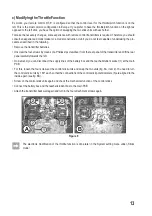
• On demand, you can disconnect the supply lines of the battery box and the teacher/student socket (1) at the main
PCB.
• For this, loosen the four screws at the control stick units and swap the two units (fig. 6A, item 2). You need to turn
the control stick units by 180° each so that the connections of the control stick potentiometers (3) are aligned to the
inside again (see fig. 6B).
• Screw on the control stick units again and check the mechanical function of the control sticks.
• Connect the battery box and the teacher/student box to the main PCB.
• Attach the transmitter back wall again and turn in the four attachment screws again.
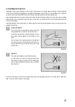
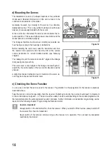
Figure 6
The electronic modification of the throttle function is done later in the System setting menu under „Sticks
mode“.
Summary of Contents for HT-6
Page 1: ... Remote Control HT 6 2 4 GHz Item no 1310037 Version 04 15 7 ...
Page 69: ...69 ...
Page 70: ...70 ...
Page 71: ...71 ...

