B-S
ERIES
I
NSTALLATION
, O
PERATION
AND
S
ERVICE
M
ANUAL
62 of 147
Step 12.3.12
For inlet hoods
w
ith permanent al
u
min
u
m mesh filters, the instr
u
ctions end here.
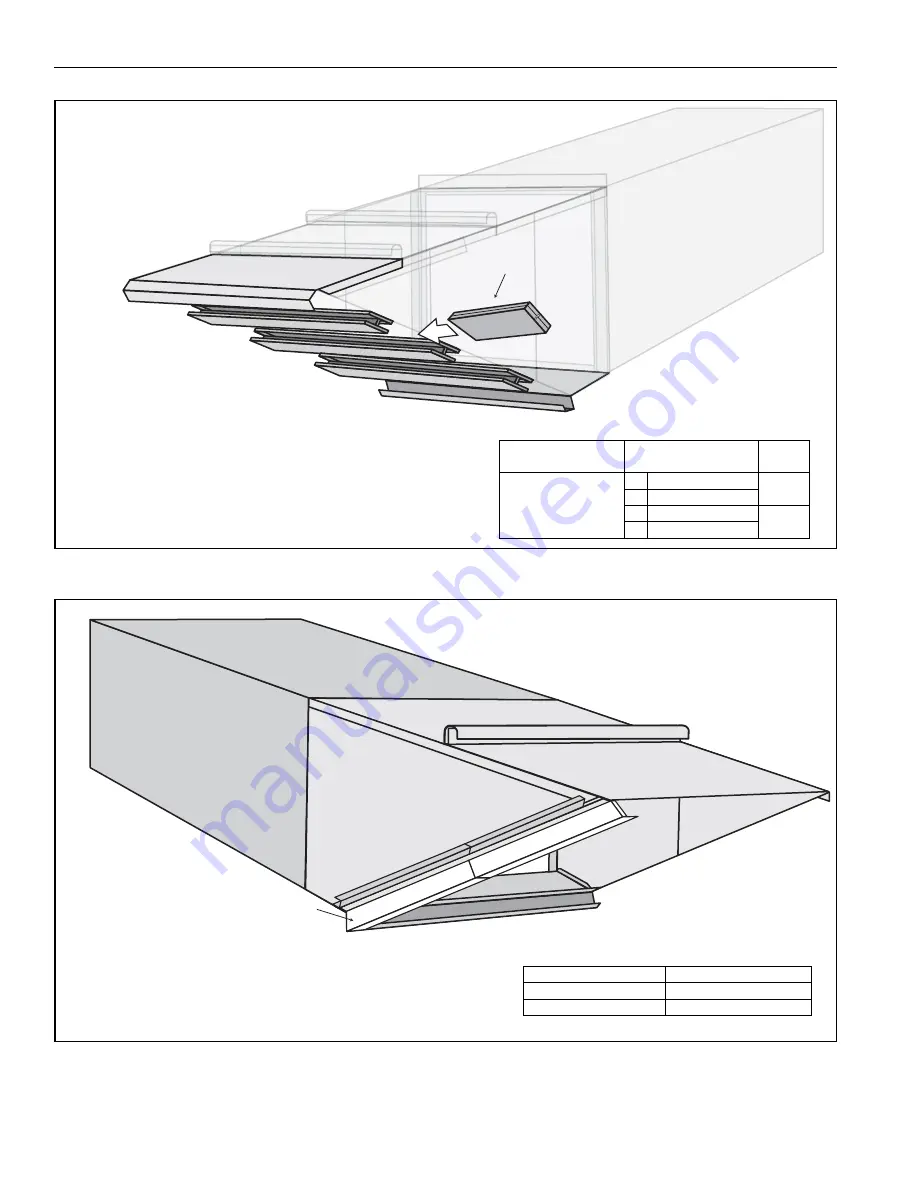
Step 12.3.13
Filter
Load filters into the inlet hood, checking
to see that each filter is in the proper orientation
by
v
erifying that the arro
w
on the side of the filter points in
the direction of air flo
w
. All of the arro
w
s sho
u
ld be
pointing to
w
ards the air handler
w
hen installed in the
proper orientation. Once filters are installed, close snap
fasteners installed pre
v
io
u
sly (
to hold filters in place.
Description
Size
Part
Number
Permanent Al
u
min
u
m
Mesh Filter
in
20 x 25 x 1
20629
cm
50.8 x 63.5 x 2.5
in
20 x 20 x 1
20628
cm
50.8 x 50.8 x 2.5
Moisture Limiter Side Cover
Attach side co
v
er of moist
u
re limiter frame to the left side
of the inlet hood drip rail
u
sing eight TEK scre
w
s. Attach
to the bottom pan assembly
w
ith t
w
o #10-24 x ½" bolts
and #10-24 n
u
ts.
Description
Part Number
Left Side Co
v
er (ML)
13205078 / 13305078
TEK Scre
w
13404
Summary of Contents for 2005
Page 2: ......
Page 4: ......
Page 8: ......
Page 10: ......
Page 31: ...SECTION 7 ROOF CURB 21 of 147 FIGURE 12 Curb Mounting Air Handler Roof Curb Fastening Detail...
Page 154: ...B SERIES INSTALLATION OPERATION AND SERVICE MANUAL 144 of 147...
Page 158: ......
Page 160: ......
Page 161: ......
Page 162: ......


