B-S
ERIES
I
NSTALLATION
, O
PERATION
AND
S
ERVICE
M
ANUAL
112 of 147
Table 1
8
: Factory Preset Schedule on TH
8
110 Thermostat
1
8
.2.4 BMS-Ready Control Option
The BMS-ready option pro
v
ides inp
u
ts to recei
v
e
control signals from a c
u
stomer determined control
system. Each BMS inp
u
t is capable of recei
v
ing a
4-20mA or 0 - 10VDC from the control system. On all
air handlers, the b
u
rner mod
u
lation
w
ill be controlled
by the control system. For AM/VAV style air handlers,
the control system can also control the mod
u
lating
damper.
On DDC/BMS-ready systems, no temperat
u
re control
amplifier is installed. Discharge temperat
u
re
monitoring and mod
u
lation
v
al
v
e adj
u
stment are
completed by the c
u
stomer s
u
pplied control system.
For optim
u
m efficiency, Rapid Engineering LLC
s
u
ggests to limit the discharge temperat
u
re to 160 °F.
1
8
.3 Basic Air Handler Se
q
uence of Operation
While the control transformer is energized, the
secondary side s
u
pplies 115 VAC to the control
circ
u
it. When the fan s
w
itch is in the "on" position, the
M1 motor starter is energized and starts the blo
w
er
motor. The M1 motor starter a
u
xiliary contact
s
u
pplies
v
oltage to the b
u
rner s
w
itch and "Fan On"
light. When the b
u
rner s
w
itch is in the "on"/"
w
inter"
position, po
w
er is s
u
pplied to the flame control
mod
u
le and the b
u
rner control circ
u
it. The b
u
rner
control circ
u
it incl
u
des the high temperat
u
re limit
s
w
itch and the lo
w
and high airflo
w
press
u
re
s
w
itches. Once the b
u
rner control circ
u
it is satisfied,
then the flame control mod
u
le
w
ill exec
u
te the b
u
rner
ignition seq
u
ence. Once the pilot flame is ignited and
sensed by the UV scanner, the flame control mod
u
le
w
ill open the safety sh
u
toff
v
al
v
e to ignite the main
flame. When the safety sh
u
toff is opened, 115 VAC is
applied to the "B
u
rner On" light and T3 transformer,
the secondary side s
u
pplies 24 VAC to the
temperat
u
re control amplifier. The temperat
u
re
control amplifier controls the mod
u
lating
v
al
v
e based
on the discharge temperat
u
re monitor (and also the
room temperat
u
re monitor, in the case of a DTC
remote panel).
1
8
.3.1 Flame Control
The flame control is a safety de
v
ice and not
ser
v
icable. See
for detailed seq
u
ence of operation.
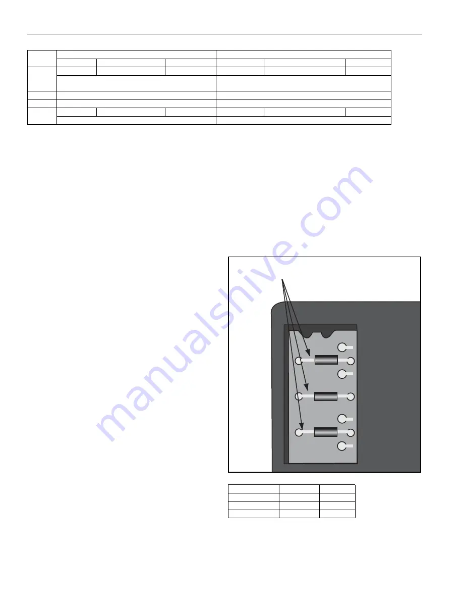
The RM 7890 and RM 7897 m
u
st be config
u
red prior
to replacement. This is done by remo
v
ing certain
config
u
ration j
u
mpers on the
u
pper left corner of the
flame control, located behind the bl
u
e co
v
er.
FIGURE 72: Honeywell Safe
g
uard Jumpers
Table 19: Site-Confi
g
uration Jumper Options
Monday - Friday
Saturday - Sunday
Time
Temperature
Fan Settin
g
Time
Temperature
Fan Settin
g
Wake
6:00 AM
68° F
Fan On
6:00 AM
62° F
Fan A
u
to
The air handler
w
ill r
u
n contin
u
o
u
sly.
Temperat
u
re controlled by Maxitrol stat.
The air handler
w
ill r
u
n
w
hen the thermostat calls for heat.
Leave
Un
u
sed
Un
u
sed
Return
Un
u
sed
Un
u
sed
Sleep
5:00 PM
62° F
Fan A
u
to
5:00 PM
62° F
Fan A
u
to
The air handler
w
ill r
u
n
w
hen the thermostat calls for heat.
The air handler
w
ill r
u
n
w
hen the thermostat calls for heat.
Jumper Number
7
8
90
7
8
97
JR1
Intact
Intact
JR2
Remo
v
e
Remo
v
e
JR3
Intact
Intact
JR1
JR2
JR3
Selectable Configuration Jumpers
Summary of Contents for 2005
Page 2: ......
Page 4: ......
Page 8: ......
Page 10: ......
Page 31: ...SECTION 7 ROOF CURB 21 of 147 FIGURE 12 Curb Mounting Air Handler Roof Curb Fastening Detail...
Page 154: ...B SERIES INSTALLATION OPERATION AND SERVICE MANUAL 144 of 147...
Page 158: ......
Page 160: ......
Page 161: ......
Page 162: ......


