tighten
Oil leakage
a. Bolt loose in interface
b.
Sealings failure
change
noise
change
a.Gear damage
b.
Bearing damage
change
2.3 Fluid transmission and torque converter
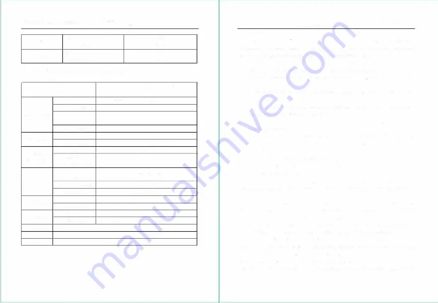
2 3 I Technical data
.
.
Model
PSI 2.4L Engine
Type
Y JH265 single-stage, two-phase, 3-element
Max. torque ratio KO
3
Torque converter
Circulating circle
diameterD
265
Peak efficiency
0.79
Fuel feed pump
type
Internal gear type
Rate of flow
271/min(2000rpm, 218psi)
Fluid
type
Power gear shifting
transmission
Speed ratio
I.35/1.35
(forward/reverse)
Friction platexinner
125x8Ix2.7mm
diameterxthickness
Fluid clutch
Size of friction plate
71cm
2
Set pressure
150-204psi
Speed reducer
Reducing gear
Spiral bevel gear
Reducing ratio
2.1
differential
Reducing gear
Straight gear,
speed ratio 6.182
Differential gear
Straight bevel gear
weight
1.85
Oil capacity
7.5 L
Oil type
No. 6 or 8 fluid driving shaft
93
2.3.2 Overview
2~3.5t fluid transmission forklift adopts introduced technology YQX30(A) fluid
transmission device which consists of fluid torque converter and power gear shifting transmission
with one forward gear and one reverse gear. It has advantages listed below:
A .. Fluid torque converter gives the fluid driving box automatic adaptability of fluid transmission
output. It can change the output torque and speed according to load change.
B .. It can absorb and remove the impacting vibration that the engine and outer load give to
transmission system.
C .. The slight moving valve enables the truck slight operation in both low speed and high speed
of engine, so that to reduce the working intensity of the operator.
D.. The fluid clutch installs 4 pairs friction plate and space board which are specially bandied to
improve the abrasive resistance of friction plate.
E .. The one-way exceeding clutch installed in torque converter oil line improves the power
transmission efficiency.
The fluid transmission consists of transmission, speed reducer and differential. The speed reducer,
differential are the same with mechanical driving forklift (see chapter 2.2)
2.3.3 Fluid transmission device
A, fluid transmission oil line diagram (Fig. 2-3)
B, fluid transmission structure diagram (Fig. 2-4)
2.3.4 Fluid transmission oil line
After starting the engine, the oil supply pump sucks the oil out of oil tank (bottom of the
transmission) through oil filter. The pressure oil is supplied for two parts: fluid clutch and torque
converter.
The oil needed for fluid clutch operation flows into constant pressure valve (the valve pressure
set as (200-204psi) and the oil flows out of it will, on the one hand, further flows into slight-moving
valve and control sliding valve, on the other hand, supply the torque converter impeller through
overflow valve (the valve pressure set 72-102psi). the oil coming from the torque converter will cool
down through oil radiator and lubricates the fluid clutch, then flows back the oil tank.
In neutral gear, the oil line from control sliding valve to clutch is closed, at this time, the constant
pressure valve opens to make the oil fully flow to torque converter through the overflow valve. When
the control sliding valve is at forward or reverse position, the oil line from sliding valve to forward
clutch or reverse clutch will connect to activate all the clutches. When one clutch works, the space
plate and friction plate in the other clutch are in separate condition, and the heat will be taken away by
94
Ranko R55 Forklift
Operator's Maintenance Manual
Common Faults & Solutions
Ranko R55 Forklift
Operator's Maintenance Manual
Common Faults & Solutions


