


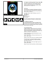


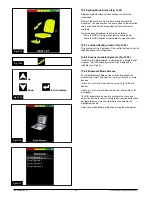


13.9 Three axis switch
and
User Switch (Fig 13.5)
Typical applications are head control systems.
The device comprises of three or four direction switches and
a User Switch connected to the
Omni2
via the 9-way D-type
connector. In addition, a normally closed User Switch
should be connected to the
Omni2
via the
1/8" (3.5mm)
mono jack
. This switch, although functionally identical to the
switch input on the 9-way D-type connector, is required to
provide a fail-safe emergency stop system.
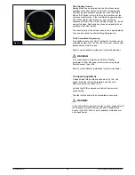
13.10 Sip and Puff Device
and
User Switch
(Fig 13.6)
A sip and puff mouthpiece is connected to the
Omni2
via the
pneumatic input. In addition, a User Switch should be
connected to the
Omni2
via the
1/8" (3.5mm)
mono jack
.
This switch is required to provide a fail-safe emergency stop
system.
Fig.13.5
Fig.13.6
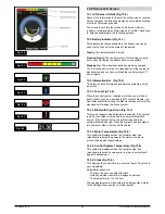
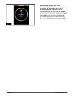
13.11 Sip and Puff Calibration (Fig 13.7)
If a new Sip and Puff SID is fitted, then the following
calibration procedure must be performed to match the Omni2
to the user’s operating capabilities.
To b
egin, contact your authorized dealer so they can access
the programming menu
. From there, follow the path detailed
below, using the right navigation button on the front of the
Omni2:
Omni – Global – Sip and Puff – Calibrate
A screen like the one shown below should appear (Fig 13.7).
Fig.13.7
Soft Sip
Soft Sip will be highlighted first. The user must now make a
series of soft sips. After each sip, a live readout of the
current pressure will be displayed on the screen in the form
of a line within the 0 - 100 scale. Repeated soft sips will
produce a ‘band’ of values. During this process it may be
beneficial for the user to look away from the screen. This
prevents ‘false’ values where the user may be trying to
attain earlier levels. Once you are satisfied
that you can
produce a soft sip consistently within this band, your
healthcare professional or authorized dealer will save that
range and move on to highlight Hard Sip
.
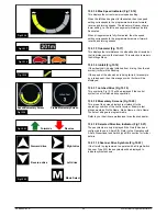
Hard Sip
The user must now make a series of hard sips to produce a
new Hard Sip band. Ideally there should be as much
difference as possible between the Soft Sip and Hard Sip
values. To aid the Omni2’s differentiation between these
pressures, the
healthcare professional / authorized dealer
should move the Threshold Marker,
(shown in Fig 13.8
opposite page),
to the middle of the gap between the
hardest soft command and the softest hard command. This
is done via the + / - buttons on the front of the Omni2. Once
a suitable threshold is set, use the right navigate button on
the front of the Omni2 to highlight Soft Puff.
249044 Rev. A
39
R-Net Control System w/Omni2
Summary of Contents for R-net
Page 1: ...Instructions for Use R Net Control System R Net Controls P N 249044 Rev A ...
Page 7: ...LED and CJSM1 249044 Rev A 7 R Net Control System w Omni2 ...
Page 34: ...Omni2 249044 Rev A 34 R Net Control System w Omni2 ...
Page 76: ...CJSM2 249044 Rev A 76 R Net Control System w Omni2 ...
Page 105: ...249044 Rev A 105 R Net Control System w Omni2 ...
Page 107: ...249044 Rev A 107 R Net Control System w Omni2 ...


