113
APPENDIX
A:
SERIAL
COMMUNICATION
Serial communication is the information exchange channel of the inverter with upper
computer. Through serial communication, users can use personal computer or industrial
control equipment (such as PLC etc) as host to set inverter (slave)’s running frequency
or command, modify or read data, read working state and fault information etc and
realize remote or centralized control of the inverter.
QD100 series inverters adopt RS-485 bus and Modbus protocol for serial communication.
A1
.
RS-485 bus
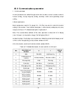
The hardware circuit of serial communication for QD100 series frequency inverter follows
RS-485 standard and a RJ45 interface is provided. Here RS-485 two-wire wiring method
is adopted. The array sequence of the corresponding pins of RJ45 interface is shown as
below:
8
1
Figure A.1 RJ45 front view
Table A.1 Pin output signal allocation
Pin
Signal description
1
Reserved
2
Common port (signal ground & power ground)
3
Reserved
4
A (RS-485+)
5
B (RS-485-)
6
Reserved
7
+24 V
8
Public terminal (Signal resource & Power resource)


