Reference
MVI56-PDPMV1 ♦ ControlLogix Platform
User Manual
PROFIBUS DPV1 Master
Page 232 of 251
ProSoft Technology, Inc.
Normal Backplane Operation
The MVI56-
PDPMV1 module’s application code initiates the data transfers at the
end of every ControlLogix PLC ladder scan. As such, the MVI56-PDPMV1
module is able to actively read and write the PROFIBUS Cyclic Input/Output data
blocks in the appropriate locations.
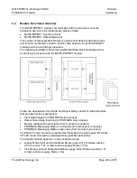
Input Data Block (Block ID = 1 to 4)
This block contains the previous input data received from the slaves.
Input Data Block Format (Input Image) (Local:1:I.Data Controller Tag)
You can find the contents of the Input Data Block (Input Image) in the
Local:1:I.Data
user controller tags in RSLogix.
Word Offset
Start
End
Name
Description
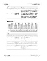
0
199
PROFIBUS Input Data Data received from the PROFIBUS slave devices on the
network.
Total size of the PROFIBUS Input Data block is a function of the
PROFIBUS network configuration.
Block ID 1 = Slave bytes 0 to 399
Block ID 2 = Slave bytes 400 to 799
Block ID 3 = Slave bytes 800 to 1199
Block ID 4 = Slave bytes 1200 to 1535
200
200
Last out mailbox
message ID processed
from output image
The module confirms the receipt of a mailbox by copying its ID
code (Message ID) to this register.
201
201
Current in mailbox
control index
Incremented after the module has transferred a new mailbox
response to the processor.
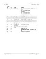
202
202
Current alarm control
index
Incremented after the module has transferred a new alarm to
the processor.
203
203
Reserved for future use
204
205
PROFIBUS CRC32
value
CRC32 checksum for PROFIBUS Master configuration
downloaded from configuration utility
206
207
Module CRC32 value
MVI56-PDPMV1 module configuration checksum for module
configuration downloaded from configuration utility
208
247
Reserved for future use
248
248
Write Block ID
Write block ID of Output image to receive (1 to 4 for data, 0 or -1
if no data)
249
249
Read Block ID
Read Block ID number -1 to 4


