


MVI56-PDPMV1 ♦ ControlLogix Platform
Reference
PROFIBUS DPV1 Master
User Manual
Page 205 of 251
ProSoft Technology, Inc.
6
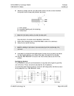
Attach the cables with the provided cable cleat to create a robust shielded
connection and to relieve any tension as shown:
J
PVC Jacket
S
Braided shielding with foil shielding
C
Cable cleat
Note
: Half of the cable jacket must lie under the cable cleat!
Pay attention to the cable cleat installation instructions.
7
Fasten the individual wires of the PROFIBUS cable to the terminals
8
Close the connector housing.
Note:
The shielding of both cables is connected internally with the metal housing of the
connector.
9
Complete the Central Shielding Measures (below) and grounding operations
for the shielding before you connect the cable connector to the module.
10
Plug the PROFIBUS DP connector into the module and secure it with the
screws.
Bus Begin and Bus End
The PROFIBUS connector with termination is required at the beginning and the
end of the bus. These connectors emulate the line impedance.
It is recommended that at least one connector with diagnostics interface is used.
Wiring diagram for a PROFIBUS DP cable


