


Reference
MVI56-PDPMV1 ♦ ControlLogix Platform
User Manual
PROFIBUS DPV1 Master
Page 198 of 251
ProSoft Technology, Inc.
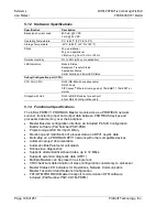
5.1.2 Hardware Specifications
Specification
Description
Backplane Current Load
800 mA @ 5 VDC
3 mA @ 24 VDC
Operating Temperature
0°C to 60°C (32°F to 140°F)
Storage Temperature
-40°C to 85°C (-40°F to 185°F)
Shock
30 g operational
50 g non-operational
Vibration: 5 g from 10 Hz to 150 Hz
Relative Humidity
5% to 95% (with no condensation)
LED Indicators
Module Status
Backplane Transfer Status
Application Status
Serial Activity and Error LED Status
Debug/Configuration port (CFG)
CFG Port (CFG)
RJ45 (DB-9M with supplied cable)
RS-232 only
CIPConnect
®
Ethernet routing using 1756-ENBT, 1756-EN2T or
similar
Shipped with Unit
RJ45 to DB-9M cables for each port
6-foot RS-232 configuration cable
5.1.3 Functional Specifications
The inRAx PDPMV1 PROFIBUS Master module acts as a PROFIBUS network
scanner, transferring input and output data between PROFIBUS devices and
processor data memory over the backplane.
Master Busview configuration interface via included ProSoft Configuration
Builder software (Part Number PSW-PCB)
Project-unique GSD file import library
Monitoring and modification of process data and DPV1 acyclic data
Multi-drop on a PROFIBUS DPV1 network with other compatible devices
Automatic project documentation
Automatic Bus Parameter calculation
Online slave diagnostics
Supports all standardized baud rates, up to 12 Mbps
Supports extended diagnostic data (DPV1)
Multiple Masters can be placed in a single rack
CRC checksum determination of slave configuration consistency to processor
Master Status LED indicators for Operations, Network Communication,
Master Token-Hold and Network Configuration
FDT/DTM PROFIBUS Master transport communication DTM software
included (Part Number PSW-CDTM-PDPM)


