background image

© Precor Incorporated, Unauthorized Reproduction and Distribution Prohibited by Law 

Page 18 


Note: If power is lost or the unit 
is no longer being pedaled 
during the rest process, the 
update process will be


interrupted, displaying a error 70 
(Belt replacement, LPCA not


read). If a error is displayed, the


Stride Count Reset process 
must be repeated.


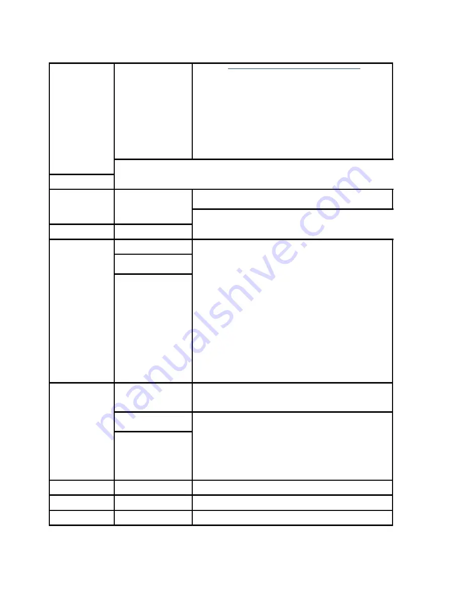
Incline/Crossr 
amp


Press the 


key 


Incline/ Crossramp will be displayed. 


Two numbers will be displayed, the percent of lift and 
A/D number related to the current lift position. The 
A/D (analog to digital) number represents the lift 
potentiometer reading. The A/ D number will be in 
the range of 0 to 255 or 0 to 32769. 


The lift may be operated using the 

INCLINE/CROSSRAMP 

keys. The incline 

percentage and A/D numbers will change 
accordingly. Care must be taken while operating the 
lift in this mode because the normal upper and lower 
range limits are not in effect. It is possible to operate 
the lift to its physical limits and may cause the lift 
motor to jam. 


Press the 

OK 

key 


Press the 

CLEAR 

key to return to 
Hardware 
Validation 


Auto  Stop 
(Treadmill 
Only)


Press the 


key 


User Detected or User Not Detected will be 
displayed. 


Press the 

OK 

key 


A magnet is attached to the running deck and a 
sensor is attached to the frame. If the sensor detects 
motion from the running deck, User Detected will be 
displayed. If the sensor does not detect motion from 
the running deck, User Not Detected will be 
displayed. 


Press the 

CLEAR 

key to return to 
Hardware 
Validation 


Summary of Contents for AMT 823

Page 1: ...Precor Incorporated Unauthorized Reproduction and Distribution Prohibited by Law Page 1 Service Manual AMT 885 835 833 823 Open Stride and Fixed 20039 172 PRECOR CUSTOMER SUPPORT...

Page 2: ......

Page 3: ...rs 24 P30 Setting Club Parameters Table 24 Documenting P30 Software Problems 27 Replacing the Upper PCA 28 Replacing the P30 Metrics PCA 35 Replacing the P30 HR PCA 37 Flash Programming the Upper PCA...

Page 4: ...Table 89 P80 Cloning Procedure 89 Replacing the P80 Console 95 Console Mounting Removal 95 Disconnection Cables 97 Console Hook and Notch 98 Cable Connections 99 Console Mounting Install 102 Replacing...

Page 5: ...cedure 117 Procedure 117 Poor Audio Quality All Channels One Limited Units 118 Description 118 Possible Causes 118 Possible Remedies 119 Poor Audio Quality All Channels Multiple Units 119 Description...

Page 6: ...ch Use 144 Daily Maintenance 144 Weekly Maintenance 145 Quarterly Maintenance 145 On Site Preventive Maintenance Service Technician 146 AMT Base Troubleshooting Procedures 147 Troubleshooting the Gene...

Page 7: ...Replacing the Front Arm Assemblies With Flat Belts and Press Fit Cams After 4 3 2013 226 Rear Flat Belt Terminal Cover Removal 232 Front Flat Belt Terminal Removal 239 Replacing a Front Arm Assembly W...

Page 8: ...ocedure 346 Replacing the H Brake Belt 348 Procedure 349 Replacing the H Brake Cam Assembly 350 Procedure 351 Replacing the H Brake Drum Assembly 356 Procedure 356 Replacing the Gas Shock 365 Replacin...

Page 9: ...bleshooting and replacement procedures required to repair and maintain this product This document contains general product information software diagnostic procedures when available preventative mainte...

Page 10: ...ck Conventions 8 General System Information 9 Warning and Caution Statements and General Safety Guidelines 9 Safety 10 General Information 11 Tools Required 11 Right Left Front and Back Conventions In...

Page 11: ...unit while voltage measurements are being taken Because of the danger of working on the unit while it is in motion using the optional external power supply is strongly recommended When the unit is us...

Page 12: ...t during AMT operation A pinching hazard exists when the unit is operated It is possible to seriously pinch a finger The AMT can be mechanically locked by inserting a screwdriver through the primary s...

Page 13: ...ure or cover Do not set anything on the handlebars display enclosure or cover Never place liquids on any part of the AMT while performing service To prevent electrical shock keep all electrical compon...

Page 14: ...le Section Three In This Section Accessing the P30 Diagnostic Software 13 Displaying P30 Information 19 Setting the P30 Club Parameters 24 Documenting P30 Software Problems 27 Replacing the Upper PCA...

Page 15: ...es the standard access codes to provide access to the various software features Use the PAUSE key and the numeric keypad to enter the access code The standard access codes use all sequential key press...

Page 16: ...OARD TEST will scroll across the display Press the OK key A representation of all of the keys on the console will be displayed Pressing a key on the console will cause the illuminated representation o...

Page 17: ...operated during this test current in amps through the drive motor belt speed in MPH and power bits PWM value This test is valuable in diagnosing treadmill load conditions such as running bed and or ru...

Page 18: ...l change accordingly Care must be taken while operating the lift in this mode because the normal upper and lower range limits are not in effect It is possible to operate the lift to its physical limit...

Page 19: ...CONTINUE PEDALING AND PRESS OK TO RESET BELT STRIDE COUNT will scroll across the display Note The STRIDE COUNT RESET is used to CLEAR the stride count to zero only when the support belts are replaced...

Page 20: ...to 32769 The lift may be operated using the INCLINE CROSSRAMP keys The incline percentage and A D numbers will change accordingly Care must be taken while operating the lift in this mode because the...

Page 21: ...e log Error Log Procedure 1 The AMT 885 835 833 and 832 uses the standard access codes to provide access to the various software features Use the PAUSE key and the numeric keypad to enter the access c...

Page 22: ...ll scroll across the display Followed by BELT USAGE Belt Usage Press the OK key BELT STRIDE COUNT XXXXXX STRIDES will be displayed followed by STRIDE COUNT RESETS XX RESETS and then ODOMETER AT LAST R...

Page 23: ...e to HOUR METER Press the OK key The operating time of the unit will be displayed as 12345 HOURS The operating time is defined as total amount of time that the unit has operated in program modes The h...

Page 24: ...The software part number will be displayed as XXXXX XXX Press the CLEAR key to exit the Metrics BOARD SW display Stride Dial SW Use the keys to move to move to STRIDE DIAL SW Press the OK key The sof...

Page 25: ...he most recent error will be displayed first Use the keys to move through the list of errors The error messages will list the error name the odometer reading when the error occurred and the hour meter...

Page 26: ...ial key presses The allowable delay between key presses are short If too much time is taken between key presses or the wrong key is pressed the access procedure will be aborted If the access is aborte...

Page 27: ...ll be displayed Set Max Workout Time Press the OK key Use the keys to select the maximum time a user can remain in a program As the keys are pressed the displayed value increments or decrements betwee...

Page 28: ...will be displayed during a workout A list of available default settings will be displayed including OFF COMPLETE TIME IN ZONE SEGMENT TIME REMAINING AVERAGE SPEED CALS MIN CALS HR WATTS METS TARGET HR...

Page 29: ...istance keys changes the resistance value for that column When this function is initiated the currently stored custom program 1 or 2 is displayed in the matrix The first column is active all the LEDs...

Page 30: ...the Upper PCA 1 Set the treadmill circuit breaker in the off position and unplug the treadmill s line cord from the AC outlet TRM only 2 The PCA s in the console are static sensitive They can be dama...

Page 31: ...ss panel to the console Figure 5 Console Access Panel 6 Remove the back access Panel a Treadmills Lift the console off the maintenance hook and then position the console so that the back panel is acce...

Page 32: ...ate PCA See Replacing the P30 HR PCA on page 37 8 Disconnect the Heart Rate Cable from the Heart Rate PCA 9 Disconnect the Data cable Auto Stop cable Treadmill only Stop Key cable Treadmill only Groun...

Page 33: ...or Incorporated Unauthorized Reproduction and Distribution Prohibited by Law Page 31 Figure 7 P30 Cable Connectors 10 Remove the two screws that fasten the back cover to the option cap and remove the...

Page 34: ...ews that fasten the rear cover from the console and remove Figure 9 Rear Console Cover 12 Disconnect the Metric cable J5 Machine Controls cable J4 Option Cap cable J6 if applicable Keypad Metric cable...

Page 35: ...lectric screw driver or over tighten the screws Over tightening may damage the console This type of damage is not covered under warranty 15 The white wire in the Metrics cable and the yellow wire in t...

Page 36: ...Metric cable and HR cable J10 from the Upper PCA board 17 Replace the P30 Rear Cover removed step 12 and secure the cover with the screws 6 screws Torque to 10 inch pounds Note Do not use an electric...

Page 37: ...ounting plate with the four screws removed in step 4 26 Fasten the dash transition cover using the two screws removed in step 3 27 Check treadmill operation as per procedure Checking the AMT Operation...

Page 38: ...Do not use an electric screw driver or over tighten the screws Over tightening may damage the console This type of damage is not covered under warranty 9 Replace the P30 Option Cap back cover removed...

Page 39: ...eldment tube making sure that the cables will not become pinched 16 Fasten the console to the dash mounting plate with the four screws 17 Fasten the dash transition cover using the two screws TRM only...

Page 40: ...nd remove the HR PCA from its mounting 5 Disconnect the HR cable and handlebar cable from the HR PCA 6 Connect the HHHR Grip cable assembly to the upper connector on the HR PCA and the HR PCA Power ca...

Page 41: ...laptop computer If a palm device is to be used it must use OS software version 3 2 or higher Currently we have only tested devices manufactured by Palm but other manufacturer s palm devices may also...

Page 42: ...onnect the PDA or computer interface cable to the CSAFE port 4 Select the software file to be uploaded on the palm device or computer 5 Start pedaling the P30 or power up using the external power supp...

Page 43: ...les are inserted into their connectors the white or yellow wire must align with the pin 1 designation on the PCA 1 Set the treadmill s on off switch in the off position Treadmill only Access the upper...

Page 44: ...CA to the display face and rotate it so that the front of the PCA is visible For treadmill s set the on off switch in the on position for AMT s EFX s UBK s RBK s and CLM s start pedaling Note There ar...

Page 45: ...A 15 If 8 Vdc is not present on J6 temporarily replace the upper PCA to power control module treadmill s or Lower PCA AMT s EFX s UBK s RBK s and CLM s cable with a known good cable 16 If the upper PC...

Page 46: ...ills Only 27 Remove the Machine Control cable from the upper PCA 28 For treadmill s set the on off switch in the on position for AMT s EFX s UBK s RBK s and CLM s start pedaling 29 If the STUCK KEY me...

Page 47: ...procedures Accessing the P30 Diagnostic Software on page 13 P80 Settings on page 51 or Accessing the Diagnostic Software Advance to the heart rate display portion of the diagnostic program Verify tha...

Page 48: ...PCA are less susceptible to radiated RF energy 8 Access the diagnostic program per procedures Accessing the P30 Diagnostic Software on page 13 P80 Settings on page 51 or Accessing the Diagnostic Soft...

Page 49: ...neither a chest strap signal or a hand held signal is being accepted with either a heart rate test transmitter or a chest strap transmitter 12 Check the plug connector connections on both the heart ra...

Page 50: ...ed in step 3 was 0 Vdc disconnect external power supply from its AC outlet and measure the voltage at the AC outlet If the AC outlet voltage is normal replace the optional external power supply If the...

Page 51: ...A 9 Reconnect the interconnect cable to the lower PCA and repeat the voltage measurement in step 8 The voltage measured should be approximately 7 5 Vdc If the voltage is significantly low the problem...

Page 52: ...In This Section P80 Settings 51 P80 About 54 P80 Equipment Usage 57 P80 System Settings 58 Updating P80 Software 61 P80 System Tests 63 P80 Connectivity 70 P80 Display 78 P80 TV Settings 81 P80 Workou...

Page 53: ...n you see when you approach the P80 console Press the Pause key and continue holding it down while you double press prior to 1 1 version software release or single press 1 1 version or after software...

Page 54: ...ess to the sign in screen Figure 20 P80 Sign In Access 2 The sign in screen will be displayed Type in the technician access 5 1 7 6 5 7 6 1 and then touch OK The Settings menu will be displayed See Se...

Page 55: ...ministrators and registered service technicians Touch Equipment Usage See Procedure P80 Equipment Usage on page 57 System Settings Use the System Settings to test your equipment and set parameters tha...

Page 56: ...es Touch next to any of the available updates Touch View to see the details of the update Touch BACK to updates list Touch Install to load the update into the console See Procedure Updating P80 Softwa...

Page 57: ...uch Event Log Details of the Event will be listed Touch REFRESH to update the list in the log Touch SAVE to save the log to a Flash drive device Touch BACK to About Event Count Number of events record...

Page 58: ...None Minimum Heartbeat Interval Minimum amount of time between heartbeats to the Preva server None None Maximum Heart beat Interval Maximum amount of time between heartbeats to the Preva server None...

Page 59: ...ocedure P80 Settings on page 51 to access the Equipment Usage menus 2 The Equipment Usage settings provide information on individual usage as well as cumulative equipment usage SeeP80 Equipment Usage...

Page 60: ...ikes will convert total revolutions to miles None None Cumulative Work Out Sessions Total number of sessions A session is counted if the summary screen displays None None Total Belt Strides AMT12 Only...

Page 61: ...Precor Incorporated Unauthorized Reproduction and Distribution Prohibited by Law Page 59...

Page 62: ...nectivity on page 70 Display The display settings allow you to configure Measurement units Standby Mode Delay Time Zone and Closed Captioning Touch Display See Procedure P80 Display on page 78 TV Sett...

Page 63: ...s location using a USB Flash drive device for P80 consoles A USB Flash drive device with pre loaded software or a web site location where you can upload the software onto a USB Flash drive device will...

Page 64: ...in the technician access code and press enter 3 Insert the USB Flash Drive into the USB Drive Port of the P80 console Figure 22 P80 USB Flash Drive Port 4 Use the System mode to configure settings in...

Page 65: ...d be installed contact PRECOR customer service 7 Touch the spot on the screen displaying Install and the P80 console will start the software installation process The software installation process can...

Page 66: ...xit to Systems Test Incline Test TRM Only 1 Touch Incline Test and then Touch START 2 Use the machine control paddle to change the lift The console will display the analog to digital A D incline posit...

Page 67: ...Precor Incorporated Unauthorized Reproduction and Distribution Prohibited by Law Page 65 3 Touch STOP to end the test Touch BACK to exit to System Tests...

Page 68: ...count of zero crossings from the generator SPM shows a software averaged version of pulse An averaged pulse per minute will display as Minimum and a Maximum pulse 3 Touch STOP to end the test Touch B...

Page 69: ...o Systems Test Touchscreen Calibration All 1 Touch Touchscreen Calibration 2 A will be displayed on a white screen Touch the the spot you just touched will disappear and then be replaced with another...

Page 70: ...Precor Incorporated Unauthorized Reproduction and Distribution Prohibited by Law Page 68 displayed colors have been touched...

Page 71: ...ll 1 Touch Numeric Display Test 2 This will test the numeric LCD display just above the paddle controls All the numeric characters will be displayed in sequence and then automatically exit to the Syst...

Page 72: ...alified contractor to set up this infrastructure This setting provides the following information Network Type Wired Default Wireless This is a selectable option but is not currently supported Configur...

Page 73: ...ific Preva Server na preva precor com P80 Connectivity Set Up and Registration Procedure 1 Before you attempt to connect to the Precor Preva Server check the status field and ensure that the Connected...

Page 74: ...uction and Distribution Prohibited by Law Page 72 Figure 23 Not Connected Connected 3 Check the IP Address field for a valid IP Address If the IP Address is present continue with step 12 If the IP Add...

Page 75: ...Precor Incorporated Unauthorized Reproduction and Distribution Prohibited by Law Page 73 Figure 24 IP Address Not Present BACK Connectivity Connection settings...

Page 76: ...ed 4 If the Status shows Connected and the IP Address is not present it will be necessary to either have the P80 software assist in acquiring the IP Address Recommended or enter the IP address manuall...

Page 77: ...already connected it will skip straight to the Network Settings screen and display the current network information Once a good IP Address has been acquired the P80 can now be registered Continue with...

Page 78: ...Law Page 76 Figure 27 Configuration Manual 9 Touch one of the network settings items from the Connectivity menu 10 Enter the data acquired from the network administrator using the on screen key pad a...

Page 79: ...reen key pad 14 Touch OK 15 A screen will appear stating the equipment is ready to be set up touch USER NAME AND PASSWORD 16 The user name and password will have been provided by Precor prior to insta...

Page 80: ...ensure the information entered is correct before completing the registration If the information is not correct touch BACK until the screen with incorrect information is displayed Make the corrections...

Page 81: ...Precor Incorporated Unauthorized Reproduction and Distribution Prohibited by Law Page 79...

Page 82: ...ton next to the selection 3 Touch OK or CANCEL to exit to the Display menu Measurement Units US Standard or Metric US Standard 1 Touch Measurement Units 2 Touch on a radio button next to either US Sta...

Page 83: ...he radio button next to the ON a dot will fill the radio button 3 Touch OK or CANCEL to exit to the Display menu Preva Net Panel ON OFF OFF 1 Touch Preva Net Panel 2 Touch on the radio button next to...

Page 84: ...the Display menu Default Channel Set a default channel for the equipment This is the channel that will display when the TV is turned on Skip Unnamed Channels On ON OFF Closed Captioning ON OFF ON 1 T...

Page 85: ...region is incorrect touch on the radio button next to appropriate region Touch OK and then touch t BACK to the TV Settings menu To scan for available channels 1 Touch Channel Guide from the TV Settin...

Page 86: ...rkout Limits The Workout Limit settings give you control over how the equipment is used Use these settings to create reasonable limitations for equipment usage including speed incline resistance and d...

Page 87: ...ng in the duration number press the back space key t key on the keypad to delete the last entry Touching the t also reactivate the presets after typing a number on the keypad 3 Touch FINISH to exit to...

Page 88: ...Precor Incorporated Unauthorized Reproduction and Distribution Prohibited by Law Page 86 radio button next to the selection 3 Touch OK to exit to the Workout Limits Settings menu...

Page 89: ...the Workout Limits screen Incline Limit TRM only TRM 883 CrossRamp incline range can be set to 0 15 TRM 885 CrossRamp incline range can be set to 0 to 15 Note the incline range is 3 to 15 but the lim...

Page 90: ...Law Page 88 EFX only from 1 to 20 2 Touch the to move auto level to the desired setting 3 Touch OK to exit to the Workout Limits menu Manage P80 Settings Cloning The only P80 console settings that ca...

Page 91: ...only CrossRamp Auto Level EFX only TV Settings Channel Guide Region Default Channel Skip Unnamed Channels Network Settings Primary DNS Manual only Secondary DNS Manual only Gateway Manual only Netmask...

Page 92: ...e The keypad X configuration sequence should be not faster than 1 second between each key stroke Any speed faster than 1 second may result in an unsuccessful access to the sign in screen Figure 29 P80...

Page 93: ...duction and Distribution Prohibited by Law Page 91 Figure 30 Manage Settings Cloning 6 The Manage Settings screen will display two gray inactive USB Flash Drive Icons 7 Insert the USB Flash Drive into...

Page 94: ...t Save to USB Note Depending on the type of Flash Drive device used it may take up to a minute for the USB Flash Drive Icons to become active light up after the USB Flash Drive device has been inserte...

Page 95: ...ack arrow until you get to the Welcome screen 12 Move the USB Flash Drive device with the saved settings to a P80 console that you would like to import the saved settings 13 Access the Manage Settings...

Page 96: ...thorized Reproduction and Distribution Prohibited by Law Page 94 Figure 34 Import From USB 16 You will see a scrolling in process bar and then Settings imported successfully displayed Figure 35 Settin...

Page 97: ...the P80 Console Required Tools 2 7 16 in open end wrenches inch hex wrench SAE inch hex wrench SAE inch box end wrench 2 Phillips screwdriver Wire cutter Console Mounting Removal 1 Remove the rear ve...

Page 98: ...ted by Law Page 96 Figure 36 P80 Rear Cover Removal 2 Remove the four flat head 5 8 inch long screws that secure the console to the plate Figure 37 Console Mounting Screws 3 Tilt the console forward a...

Page 99: ...ection Cables 1 Locate the coax connector and cut the wire tie that secures the coax connector to the console armor Disconnect the coax cable connector from the consoles flexible coax cable connector...

Page 100: ...Console Hook and Notch 1 Install the replacement console In the back of the P80 console there is a large black steel support called the Armor At the bottom of Armor there is a notch about inches in d...

Page 101: ...s shown in diagram below Feed about 10 inches of cable out though the plastic using your finger as a guide 2 Bring the coax cable up over the top of the armor and connect it to the flexible cable atta...

Page 102: ...behind the tuner and connect the Ethernet cable to the upper RJ45 type connector 5 Route the grey flat Data cable through the opening in the upper right side of the armor behind the tuner and connect...

Page 103: ...side of the P80 as shown in below as it might be necessary to access it for troubleshooting Figure 42 P80 Power Cable Routing 7 Route the Heart Rate cable through the upper left corner of the weldmen...

Page 104: ...stic guides inside the neck 2 Tilt the control console backward toward yourself until the tab on the top edge of the armor slides along the top edge of the console mount and the screw holes align prop...

Page 105: ...atic sensitive They can be damaged if proper static prevention equipment is not used Attach an anti static wrist strap to your arm and then connect the ground lead of the wrist strap to frame ground 3...

Page 106: ...porated Unauthorized Reproduction and Distribution Prohibited by Law Page 104 Figure 45 P80 Heart Rate PCA Board 7 Replace the rear vent cover 8 Check operation per procedure Checking the AMT Operatio...

Page 107: ...Precor Incorporated Unauthorized Reproduction and Distribution Prohibited by Law Page 105...

Page 108: ...116 Poor Audio Quality All Channels One Limited Units 118 Poor Audio Quality All Channels Multiple Units 119 Machine Controls Unresponsive 120 Machine Controls Incorrect Response 121 Message Out of Se...

Page 109: ...Tuner USB Cable Possible Remedies 8 Check for video signal to the tuner 9 Inspect jumper cables connecting fitness equipment to the video drop If it is visibly damaged or disconnected replace or recon...

Page 110: ...ignal to the console is good and the TV screen has been black for more than 5 10 minutes then the watchdog is not able to recover the media player If it is less than 5 minutes or so the watchdog may s...

Page 111: ...frozen 2 Console is attempting to boot to an image that has corrupted 3 Touch screen has failed Possible Remedies 1 Reboot the machine to resolve any software freezing issues 2 If the console is attem...

Page 112: ...power switch turned to the On position allowing the P80 console to boot up completely 5 If the P80 console boot up to the Welcome screen was successful go to step 6 If the P80 console still will not...

Page 113: ...e running through the machine 4 Connect the machine to a known good A V drop If the TV channel now appears on the console verify the drop is good If not have the customer contact their A V service tec...

Page 114: ...issue 4 Enter the Settings Menu Select System Settings then TV Settings Verify that unit is set for United States See P80 TV Settings on page 81 Poor Quality Video One Channel or Limited Channels Desc...

Page 115: ...to repair the drop 8 Verify signal strength with signal meter 9 As above verify condition and connections of coax cables as well as verify quality of signal to that drop Verify signal strength using a...

Page 116: ...the original channel Touch Screen Unresponsive Description Touch screen does not respond to any touches Screen may show a static or a moving image but is not completely black Possible Causes 1 Console...

Page 117: ...sion software release or single press 1 1 version or after software release in sequential order an X configuration on the Volume and Channel key pad Channel Up Volume Down Volume Up Channel Down Relea...

Page 118: ...propriately to touches but does so slowly The screen may or may not play the animations associated with the touches when carrying out the appropriate action Possible Causes 1 The console is running lo...

Page 119: ...ing so Single Secret Handshake Procedure Procedure 2 The Welcome screen will be the first screen you see when you approach the P80 console Press the Pause key and continue holding it down while you do...

Page 120: ...t the users and the facility Changes made to these settings save to the fitness equipment To select a Setting touch on an item in the Settings menu Poor Audio Quality All Channels One Limited Units De...

Page 121: ...to ensure signal from head end is within acceptable parameters 7 Troubleshoot as above Signal provider e g Cable Company Satellite Company etc will need to address this issue 8 Enter the Settings Men...

Page 122: ...through the machine 7 Connect the machine to a known good A V drop If the TV channel now appears on the console verify the drop is good If not have the customer contact their A V service technician to...

Page 123: ...ser if flipping the machine controls with a lot of force the control could rebound with enough force to cause it to bounce in the other direction causing the machine to think the user is actually pres...

Page 124: ...console Most issues causing Out of Service errors will be cleared from a reboot 4 Treadmill Only Inspect the Auto Stop sensor and ensure it is installed properly Inspect Auto Stop cable to ensure it i...

Page 125: ...h to the console is disconnected loose or damaged 4 The stop switch is malfunctioning Possible Remedies the yellow button on the dash to reset the treadmill y on 7 Inspect the connections leading from...

Page 126: ...r supply if Treadmill Swap with known good to test if needed On Treads also check from power supply to console Again swap with known good to test 8 Inspect power supply for damage Swap with known good...

Page 127: ...AMT concentrate on the operating sounds made by the unit Be on the alert for unusual rubbing hitting grinding or squeaking noises 5 Ensure that the AMT is properly leveled that the two feet are in co...

Page 128: ...e Levels 1 and 10 troubleshoot per AMT Base Troubleshooting Procedures on page 147 11 Check the LED s mounted on the upper PCA and the function keys displayed on the electronic console by performing P...

Page 129: ...e Generator Belt Tension 130 Inspecting and Adjusting the Drive Input Belt Tension 132 Calibrating the Incline Motor 137 Drive Belt Gauge Instructions 142 Measuring the Resistance of a Generator Cauti...

Page 130: ...LOAD terminals of the lower PCA 5 With an ohmmeter read between the wires removed in step 4 The reading should be approximately 10 Ohms Replace the two wires removed in step 4 6 Remove the three wire...

Page 131: ...ng with this procedure review the Warning and Caution statements listed in the Warning and Caution Statements and General Safety Guidelines Section Things You Should Know Procedure 1 Remove the gasket...

Page 132: ...h or low the belt tension may be adjusted by loosening or tightening the H Brake adjustment bolt Figure 51 H Brake Belt and H Brake Cam Inspecting and Adjusting the Generator Belt Tension WARNING Befo...

Page 133: ...cement on page 152 2 Place a belt gauge on the generator belt as shown in below Figure 52 Generator Belt 3 The belt gauge should read approximately 85 5 lbs If the belt tension is significantly high o...

Page 134: ...nsion 7 The tension should read approximately 85 5 lbs Figure 53 Generator Inspecting and Adjusting the Drive Input Belt Tension WARNING Before continuing with this procedure review the Warning and Ca...

Page 135: ...aw Page 133 Figure 54 Dive Input Belt 3 The belt gauge should read approximately 135 5 lbs If the belt tension is significantly high or low the belt tension may be adjusted by following the steps belo...

Page 136: ...ed Reproduction and Distribution Prohibited by Law Page 134 Figure 55 Generator 6 Loosen the two step up pulley mounting bolts 7 Loosen or tighten the step up pulley adjustment bolt until the belt gau...

Page 137: ...n the input mounting bolts 9 Select the QUICKSTART program and adjust the resistance key until resistance level 10 is displayed Pedal the AMT for approximately one minute then recheck the belt tension...

Page 138: ...ted by loosening the generator mounting bolts 13 Loosen or tighten the 1 4 20 X 3 generator adjustment nut and bolt until the belt gauge reads approximately 85 5 lbs 14 Tighten the two 5 16 18 X 3 gen...

Page 139: ...e top of the gas shock by pushing a 1 flat top screw driver in the slot under the tension clip Do not completely remove the retaining clip as it is difficult to reinstall Tip If the incline motor is j...

Page 140: ...p the stairarms and pull the flat belts off the flat belt pulleys and gently set the stairarms down 6 Remove the hitch pin from the incline motor mounting pin 7 Remove the incline motor mounting pin i...

Page 141: ...ncline to level 2 using the STRIDE HEIGHT and STRIDE HEIGHT keys 10 Rotate the incline motor tube on the incline motor drive screw until the measurement between the top of the incline nut and the end...

Page 142: ...ent Gas Shock Installation 11 Rotate the gas shock up 12 Adjust the height of the gas shock by lowering or raising the front of the Incline platform until the gas shock and the upper mounting stud ali...

Page 143: ...les align with the Incline platform mounting holes 15 Thread the Incline motor mounting pin through the Incline tube and Incline platform and attach the hitch pin 16 Replace the wave washer and flat b...

Page 144: ...ok engages the belt 2 Hold the gauge square to the edge of the belt and release the ball using a quick snapping motion a Gear belt tension gauge position Tension gauge finger must land on top peak of...

Page 145: ...hin manufacture s specifications seat the belt Run the machine for approximately 1 2 minutes and then re check the tension This will allow the belt to seat itself in the grooves of the pulley and ensu...

Page 146: ...tive Maintenance Owner Cleanliness of the AMT and its operating environment will keep maintenance problems and service calls to a minimum Precor recommends that you perform the following preventive ma...

Page 147: ...cing the platform Re level the AMT to ensure that the two leveling feet are in contact with the floor Thoroughly test the AMT per Checking the AMT Operation on page 125 including heart rate Cardio The...

Page 148: ...reading Check stride rate and stride length sensor function is the stride rate and stride length displayed when the unit is in operation Visually inspect the drive belts and flat belts for cracks fra...

Page 149: ...s used to charge the AMT s internal battery Lastly one of the generators six phase output windings is monitored to determine when the unit is in use and when it is idle This system also determines the...

Page 150: ...otentiometer is rotated via an internal gear drive system The potentiometer s changing resistance is fed to the incline control system and converted to an A D analog to digital number that is used in...

Page 151: ...J3 connector on the lower PCA as follows voltmeter common lead to terminal 3 black wire and voltmeter hot lead to terminal 2 red wire Using the STRIDE HEIGHT keys operate the incline The voltmeter sho...

Page 152: ...t the diagnostics program and leave the unit idle long enough for it to shut off Disconnect the red battery lead from terminal M6 of the lower PCA Remove the intermediate cable from the J3 connector o...

Page 153: ...Incorporated Unauthorized Reproduction and Distribution Prohibited by Law Page 151 6 If you have performed all of the procedures above and have been unable to correct the problem call Precor customer...

Page 154: ...placing the Lower Board 268 Replacing the Lower PCA and Battery Bracket 270 Replacing the Battery 272 Replacing the Generator Belt 273 Replacing the Generator 278 Replacing the Drive Input Pulley Belt...

Page 155: ...er gasket with your thumbs until the gasket locking tabs are free of the top cover grasp the gasket and remove The gasket is split at the back to facilitate removal Figure 65 Cover Gasket 2 Grasp the...

Page 156: ...ose end of the top cover up to apply slight pressure on the locking tabs With the heel of your hand gently tap the back cover just below the top cover see figure below The top cover should release fro...

Page 157: ...triangle markers embossed into the left and right side covers the markers indicate locking joints Place the heels of your hands just above the left and right side triangle markers Gently tap the tria...

Page 158: ...ter beam cover back toward you until the cover is free from the frame Note Do not lift the cover up right after the front cover tab releases lifting up the cover too quickly may not allow the middle c...

Page 159: ...bottom lift up and then pull the bottom of the cover out and away from the frame The cover will release from the locking tabs 2 Rotate the bottom of the side cover towards the back of the AMT to remov...

Page 160: ...right bottom covers in place align the cover mounting holes 2 Fasten the two covers together with the 8 10 x inch screws Left and Right Side Cover Assembly 1 Grasp the side cover near the bottom rota...

Page 161: ...on the bottom cover 5 Repeat the Side Cover Assembly procedure for the right side cover Figure 75 Side Cover Assembly Back Cover Assembly 1 Hold the back cover up against the frame of the AMT in the...

Page 162: ...e engaged Figure 77 Back Cover Locking Tab Center Beam Cover Assembly 1 Set the center beam cover over the frame beam so that the front of the center beam cover is about 3 inches away from the bottom...

Page 163: ...lick into place 2 Fasten the two 10 x inch screws at the bottom corners of the front cover Tighten the screws completely Upper Arm Cover Replacement Figure 78 Upper Arm Covers Procedure 1 Remove the f...

Page 164: ...l remove the outside terminal cover 2 Rotate the inside terminal cover down until it is below the stairarm pedal pull to remove 3 Align the top of the replacement inside cover so that it is pointing t...

Page 165: ...eplacement 1 Slide the vertical handlebar boot cover up the handlebar to gain access to the upper arm cam cover screws 2 Remove the two screws that secure the upper arm cam covers to the upper arm rem...

Page 166: ...ly 2 Gently snap the front edge of the top cover into place using the heel of your hand if necessary 3 Wrap the gasket around the center fame column below the heart rate sensor grips then fit it into...

Page 167: ...er arm 3 Remove the inside and outside covers from the upper arm 4 Repeat the process for the remaining upper arm covers Figure 83 Upper Arm Cover Screw Locations Belt Guard Removal 5 Grasp the belt g...

Page 168: ...pieces and needs to be separated before it can be removed from flat the belt a Lower the belt guard down just below the upper arm b Squeeze the belt guard near the base to release locking tabs and rot...

Page 169: ...front of the machine and the guard toward the back The rear belt guard should be positioned with the guard toward the front Align the interlocking tabs of the front belt guard with the slots of the r...

Page 170: ...d Distribution Prohibited by Law Page 168 Figure 87 Belt Guard Mounting 9 Replace the upper arm covers as per procedure Upper Arm Cover Replacement on page 161 Replacing the Upper Arm Grip Upper Arm G...

Page 171: ...hibited by Law Page 169 Figure 88 Upper Arm Covers 1 Remove the four screws that fasten the inside upper arm covers to the upper arm 2 Remove the screw that fasten the outside upper arm covers to the...

Page 172: ...Repeat the process for the remaining upper arm covers Figure 89 Upper Arm Cover Screw Locations Belt Guard Removal 5 Grasp the belt guard mounting ring s located on each side of the upper arm Gently p...

Page 173: ...interlocking halves and needs to be separated before it can be removed from flat belt a Lower the belt guard down just below the upper arm b Squeeze the belt guard near the base to release locking ta...

Page 174: ...bution Prohibited by Law Page 172 7 Repeat the process for the remaining belt guard Figure 91 Belt Guard Removal Upper Arm Grip Removal 8 Remove the two 10 24X 75 screws that secure the grip to the up...

Page 175: ...roduction and Distribution Prohibited by Law Page 173 Figure 92 Upper Arm Grip Screw Locations 9 Grasp the grip connecting ring located on each side of the upper arm pull up and over the flat belt pul...

Page 176: ...crews Repeat the process for the remaining upper arm grip Belt Guard Installation 12 Place the two halves of the belt guard so they are positioned around the flat belt just below the upper arm The sma...

Page 177: ...Replace the upper arm covers as per procedure Upper Arm Cover Replacement on page 161 Replacing a Flat Belt Terminal Flat Belt Terminal Replacement Procedure Rear Flat Belt Terminal Cover Removal 1 R...

Page 178: ...ove the tension from the inner flat belt pulleys by lifting up on the stairarms pulling the flat belts off the flat belt pulleys and then gently setting the stairarm down 5 Remove the flat belt termin...

Page 179: ...terminal onto the stairarm using the washer and mounting bolt removed in step 5 torque to 300 inch pounds 25 ft lbs or 25 foot pounds 10 Fasten the stop bolt and washer to the flat belt clamp but do n...

Page 180: ...t Measurement 15 If the measurement is too low or too high tighten or loosen the adjustment bolt until the 3 7 8 inch measurement is achieved Figure 99 Flat Belt Terminal Adjustment 16 Repeat the proc...

Page 181: ...over up and in to place 2 Fasten the outside and inside terminal cover to the flat belt terminal using the two 10 24 X 1 25 screws Figure 100 Flat Belt Terminal Covers Replacing a Upper Arm Flat Belt...

Page 182: ...ibited by Law Page 180 Figure 101 Upper Arm Covers 3 Remove the four screws that fasten the inside upper arm covers to the upper arm 4 Remove the screw that fasten the outside upper arm covers to the...

Page 183: ...epeat the process for the remaining upper arm covers Figure 102 Upper Arm Cover Screw Locations Belt Guard Removal 7 Grasp the belt guard mounting ring s located on each side of the upper arm Gently p...

Page 184: ...o interlocking halves and needs to be separated before it can be removed from flat belt a Lower the belt guard down just below the upper arm b Squeeze the belt guard near the base to release locking t...

Page 185: ...d by Law Page 183 9 Repeat the process for the remaining belt guard Figure 104 Belt Guard Removal 10 Remove the 3 8 16 X 3 mounting bolt the two washers and the 3 8 16 lock nut that secure the upper a...

Page 186: ...per arm 13 Secure the flat pulley assembly to the upper arm using the mounting bolt washers and lock nut Thread the mounting bolt from the inside of the upper arm towards the outside of the upper arm...

Page 187: ...oward the front of the machine and the guard toward the back The larger half should be positioned with the guard toward the front Align the interlocking tabs of the smaller half with the slots of the...

Page 188: ...on 18 Secure the upper arm covers to the arm weldment using the five 10 24X1 25 screws Figure 108 Upper Arm Cover Screw Locations 19 Lift the stairarms and then thread the flat belts over the flat bel...

Page 189: ...more efficient if a assistant holds the stairarm up 2 Remove the four screws washers and washer plate that secure the stairarm pedal to the stairarm remove the stairarm pedal 3 Fasten the replacement...

Page 190: ...Precor Incorporated Unauthorized Reproduction and Distribution Prohibited by Law Page 188 Figure 110 Stairarm and Stairarm Pedal Screw Locations Replacing a Stairarm...

Page 191: ...ure Rear Flat Belt Terminal Cover Removal 1 Remove the two 10 24 X 1 25 screws that secure the flat belt terminal covers to the flat belt terminal remove the outside terminal cover 2 Rotate the top of...

Page 192: ...hibited by Law Page 190 Figure 112 Flat Belt Terminal Covers Flat Belt Terminal Removal 4 Remove the mounting bolt and washer that secure the flat belt terminal to the stairarm remove the flat belt te...

Page 193: ...it You may have to rotate the bearing one full turn to align the bearing lock hole with drain hole 6 Once the screwdriver has locked the bearing preventing further rotation fully remove the inside and...

Page 194: ...by Law Page 192 Figure 115 Stairarm and Stairarm Pedal Screw Locations Stairarm Knuckle Cover Removal 9 Remove the two 10 24 X 75 screws that secure the stairarm knuckle cover to the stairarm and set...

Page 195: ...screws Figure 117 Stairarm and Stairarm Pedal Screw Locations 13 Position the stairarm in the front arm 14 Place the shaft of a Philips screw driver into the drain hole on the bottom of the front arm...

Page 196: ...ng the washer and mounting bolt torque to 300 inch pounds 25 ft lbs or 25 foot pounds Figure 118 Flat Belt Terminal Removal Rear Flat Belt Terminal Cover Installation 18 Align the top of the replaceme...

Page 197: ...belts The two outside flat belts are routed from the stairarm terminals up over a flat belt pulley and through the upper arm terminating at the upper arm cams The inside flat belts are routed from th...

Page 198: ...at a time If you are swapping a PCA board to perform troubleshooting note the process below to prevent the stride count odometer from being prematurely overwritten When you stop pedaling the AMT the A...

Page 199: ...Precor Incorporated Unauthorized Reproduction and Distribution Prohibited by Law Page 197...

Page 200: ...is less than that of the UPCA and the UPCA is less than 30 000 strides The LPCA stride count record is written to the UPCA 75 LPCA stride count is less than 30 000 strides and is lower than that of t...

Page 201: ...ver Replacement on page 152 2 Remove the screw that secures the belt keeper to the frame and remove the belt keeper 3 Remove the tension from the inner flat belt pulleys by lifting up on the stairarms...

Page 202: ...e the removal and installation of the flat belts 6 Remove and discard the two 1 4 20X1 flat belt clamp screws and shims that secure the flat belt to the clamp Figure 122 Front Belt Clamp Screw Removal...

Page 203: ...oved from the flat belt clamp or cams the screws must be discarded and replaced with new screws 9 Remove and discard the two 1 4 20X1 flat belt cam clamp screws and shims that secure the flat belt to...

Page 204: ...inches Using a straight edge and permanent marker draw a line across the flat belt at 10 inches Repeat this process for the other end of the flat belt Figure 126 Flat Belt End Measurement 12 Place th...

Page 205: ...elt end on the 10 inch mark work the loop into the cam clamp A 1 2 inch deep set socket can be used to assist in pushing the belt into place When the flat belt loop is about half way into the cam clam...

Page 206: ...do not fully tighten at this time Inside Flat Belt Routing 17 Route the flat belt over the top of the cam towards the back of the AMT and down over the first flat belt pulley then under the second fl...

Page 207: ...the flat belt to the 10 inch mark While holding the flat belt end on the 10 mark work the loop into the terminal belt clamp A 1 2 inch deep set socket can be used to assist in pushing the belt into pl...

Page 208: ...lts ends will now need to be adjusted to their final position before the flat belt clamp screws can be tightened Gently press downward on the stairarm pedal that corresponds to the replacement belt 23...

Page 209: ...rement Torque to 120 inch pounds 26 Resume applying downward pressure to the stairarm pedal until the remaining flat belt end reaches the one segment measurement Tighten the two flat belt screws and t...

Page 210: ...per Arm Cover Removal Figure 132 Upper Arm Covers 1 Remove the four screws that fasten the inside upper arm covers to the upper arm 2 Remove the screw that fasten the outside upper arm covers to the u...

Page 211: ...ohibited by Law Page 209 Figure 133 Upper Arm Cover Screw Locations Belt Guard Removal 1 Grasp the belt guard mounting ring s located on each side of the upper arm Gently pull out and away from the gr...

Page 212: ...parated before it can be removed from flat belt a Lower the belt guard down just below the upper arm b Squeeze the belt guard near the base to release locking tabs and rotate the two halves down c Tak...

Page 213: ...p Removal 4 Remove the two screws that secure the grip to the upper arm there is one screw on each side of the upper arm Figure 136 Upper Arm Grip Screw Locations 5 Grasp the grip connecting ring loca...

Page 214: ...upper arm grip Rear Flat Belt Terminal Cover Removal 7 Remove the two 10 24 X 1 25 screws that secure the flat belt terminal covers to the flat belt terminal remove the outside terminal cover 8 Rotate...

Page 215: ...Covers Flat Belt Removal Rear Terminal Note Any time the flat belt terminal screws are removed from the flat belt clamp or cams the screws must be discarded and replaced with new screws 10 Remove and...

Page 216: ...A 1 2 inch socket will fit the inside diameter of the flat belt clamp and can be used to push the flat belt out of the flat belt clamp Figure 140 Flat Belt Pin Removal Upper Arm Flat Belt Pulley Remo...

Page 217: ...rm 12 If the flat belt cannot be pulled through the upper arm by taping a new belt to the old belt or with a fish tape continue with the next steps otherwise skip to the Flat Belt Removal Upper Arm Ca...

Page 218: ...Arm Flat Belt Pulley Removed Flat Belt Removal Upper Arm Cam Note Any time the flat belt terminal screws are removed from the flat belt clamp or cams the screws must be discarded and replaced with ne...

Page 219: ...Distribution Prohibited by Law Page 217 Figure 143 Upper Outside Cam Screw Removal 17 Using a screwdriver push out the pin from the flat belt loop and cam clamp and then slide the flat belt out of the...

Page 220: ...r coat hanger to pull the belt through the upper arm Ensure the flat belt is routed over the top of any hardware that may be crossing the inside of the upper arm 18 Grasp the loose end of the flat bel...

Page 221: ...ht edge and permanent marker draw a line across the flat belt at 10 inches Repeat this process for the other end of the flat belt 20 Place the inside flat belt on the cam so the length of the flat bel...

Page 222: ...0X1 replacement screw and shim that secures the flat belt to the cam Do not tighten fully at this time Flat Belt Pulley Installation 25 Slide the pulley shaft into the flat belt pulley and place one s...

Page 223: ...push the pin into the flat belt loop 30 Continue to work the flat belt loop and pin into the terminal clamp until the side of the flat belt is resting next to the clamp screw Ensure the pin is centere...

Page 224: ...lt end that has reached the one segment measurement Torque to 120 inch pounds Resume applying downward pressure to the stairarm pedal until the remaining flat belt end reaches the one segment measurem...

Page 225: ...t Measurement 39 If the measurement is too low or too high tighten or loosen the adjustment bolt until the 3 7 8 inch measurement is achieved Figure 151 Flat Belt Terminal Adjustment 40 Repeat the pro...

Page 226: ...so they are positioned around the flat belt just below the upper arm The smaller half should be positioned so that the interlocking tabs are pointing toward the front of the machine and the guard towa...

Page 227: ...Upper Arm Cover Installation 46 Secure the upper arm covers to the arm weldment using the five 10 24X1 25 screws Figure 153 Upper Arm Cover Screw Locations 47 Replace the Upper Arm Cam Covers as per p...

Page 228: ...12 Replacing the Front Arm Assemblies With Flat Belts and Press Fit Cams After 4 3 2013 1 Standing at the front of the AMT push in and then downward on the cover gasket with your thumbs until the gask...

Page 229: ...ull the loose end of the top cover up to apply slight pressure on the locking tabs With the heel of your hand gently tap the back cover just below the top cover see figure below The top cover should r...

Page 230: ...here are two triangle markers embossed into the left and right side covers the markers indicate locking joints Place the heels of your hands just above the left and right side triangle markers Gently...

Page 231: ...center beam cover back toward you until the cover is free from the frame Note Do not lift the cover up right after the front cover tab releases lifting up the cover too quickly may not allow the midd...

Page 232: ...rom the frame The cover will release from the locking tabs 8 Rotate the bottom of the side cover towards the back of the AMT to remove 9 Repeat steps 1 and 2 to remove the right side cover 10 Remove t...

Page 233: ...y lifting up on the stairarms pulling the flat belts off the flat belt pulleys and then gently setting the stairarm down Upper Arm Cam Cover Removal 14 Remove the two 10 24X1 25 screws that secure the...

Page 234: ...t belt terminal covers to the flat belt terminal remove the outside terminal cover 17 Rotate the top of the inside terminal cover down until it is below the stairarm pedal pull to remove 18 Repeat the...

Page 235: ...Figure 162 Flat Belt Clamp and Flat Belt Terminal Upper Arm Cover Removal 2 Remove the four screws that fasten the inside upper arm covers to the upper arm 3 Remove the screw that fasten the outside u...

Page 236: ...on Prohibited by Law Page 234 Figure 163 Upper Arm Cover Screw Locations 1 Repeat the steps for the remaining front arm covers Upper Arm Grip Removal 2 Remove the two screws that secure the grip to th...

Page 237: ...roduction and Distribution Prohibited by Law Page 235 Figure 164 Upper Arm Grip Screw Locations 3 Grasp the grip connecting ring located on each side of the upper arm pull up and over the flat belt pu...

Page 238: ...er Arm Grip Removal 4 Repeat the steps for the remaining front arm grip Belt Guard Removal 5 Grasp the belt guard mounting ring s located on each side of the upper arm Gently pull out and away from th...

Page 239: ...guard down just below the upper arm b Squeeze the belt guard near the base to release locking tabs and rotate the two halves down c Taking care to not lose the rollers inside the belt guard pull the t...

Page 240: ...roduction and Distribution Prohibited by Law Page 238 Figure 168 Upper Arm Flat Belt Pulley Mounting 8 Slide out the upper arm pulleys the two spacers and the pulley shaft from the upper arms Figure 1...

Page 241: ...to the drain hole on the bottom of the front arm Rotate the front arm bearing by turning the outside mounting bolt that secures the front arm to the stairarm until the screw driver engages into the be...

Page 242: ...n Prohibited by Law Page 240 Figure 171 Stairarm and Front Arm Screw Locations 13 Remove the vertical handle bars Tie Rod Removal 14 Remove the tie rod mounting bolts and washers that secure each uppe...

Page 243: ...cam tubes to the upper arms Note This step must be performed before the main shaft clamp is removed otherwise the shaft will rotate when the bolt is turned and you will not be able to be remove the bo...

Page 244: ...nt belt to the old flat belt at the cam side and then pull the new belt through the upper arm as the old belt is removed If the belt has already been removed you can use a fish tape or coat hanger to...

Page 245: ...the right front arm assembly next to one of the front arms while feeding the outside flat belt through the upper arm Note the flat belt must be routed over the strut in the front arm assembly Failure...

Page 246: ...ing Transparent View of Arm 20 With assistance lift the front arm and place it into the main shaft clamp and upper arm Repeat the process for the remaining front arm assembly Figure 177 Front Arm Shaf...

Page 247: ...Bolt 22 Insert and finger tighten the six main arm shaft bolts that secure the main shaft clamp to the lower main shaft clamp 23 Use the following sequence to ensure the upper arm main shaft is prope...

Page 248: ...eat the steps for the remaining flat belt pulley Note The lock nut should be on the outside of the upper arm Upper Arm Grip Installation 28 Grasp the grip connecting ring located on each side of the u...

Page 249: ...ont arm 36 Place the shaft of a Philips screw driver into the drain hole on the bottom of the front arm and thread one of the two 1 2 13X1 screws into stairarm Using the installed screw rotate the fro...

Page 250: ...by Law Page 248 Figure 181 Stairarm and Front Arm Screw Locations Flat Belt Routing 40 Ensue the flat belts are routed correctly through the pulleys See illustration below for proper flat belt routing...

Page 251: ...ion and Distribution Prohibited by Law Page 249 Figure 183 Front Belt Clamps Tie Rod Installation 42 Fasten each upper tie rod end to the cam assembly using the bolts and washers torque the bolt to 30...

Page 252: ...belt terminal 44 Push one of the stairarm pedal s down to its lowest level Measure the distance from the bottom of the stairarm tube to the top of the center beam frame the distance between the staira...

Page 253: ...le bars 51 At the console enter the access code PAUSE 5 1 7 6 5 7 6 1 to enter into the diagnostics software Navigate to the STRIDE COUNT RESET section and reset the flat belt stride count 52 Fully ch...

Page 254: ...move the tension from the inner flat belt pulleys by lifting up on the stairarms pulling the flat belts off the flat belt pulleys and then gently setting the stairarm down Upper Arm Cam Cover Removal...

Page 255: ...utside mounting bolt that secures the front arm to the stairarm until the screw driver engages into the bearing and locks it You may have to rotate the bearing one full turn to align the bearing lock...

Page 256: ...ms the screws must be discarded and replaced with new screws 7 Remove and discard the two 1 4 20X1 flat belt cam clamp screws and shims that secure the flat belt to the clamp Figure 188 Upper Inside C...

Page 257: ...e process to remove the outside flat belt from the front arm cam Tie Rod Removal 10 Remove the tie rod mounting bolt and washer that secures the upper tie rod end to the upper arm axle Figure 190 Tie...

Page 258: ...Page 256 Figure 191 Front Arm Mounting Bolt 12 Remove the six bolts that secure the upper main shaft clamp to the lower main shaft clamp Remove the top main shaft clamp Figure 192 Main Shaft Clamp Bol...

Page 259: ...removing the cams note the orientation on the front arm 1 Mark the sides of the inside and outside cams with a notation to indicate the sides facing away from the front arm tube For example mark the o...

Page 260: ...one sides of the front arm tube Align the flat belt cam alignment slot with the square key mounted in the front arm tube slide the flat belt cam onto the front arm tube Do not use excessive force to...

Page 261: ...Prohibited by Law Page 259 Figure 195 Front Arm and Cam Square Keys 4 Note ensure the flat belts are positioned correctly before installing the front arm With assistance lift the front arm and then s...

Page 262: ...bolt for the outside cam tube to the upper arm 6 Use the following sequence to ensure the upper arm main shaft is properly secures to the front arm shaft torque the bolts to 160 inch pounds Figure 19...

Page 263: ...tion and Distribution Prohibited by Law Page 261 Figure 198 Front Arm Mounting Bolt Tie Rod Installation 8 Fasten upper tie rod end to the cam assembly with the bolt and washer torque the bolt to 300...

Page 264: ...ross the flat belt at 4 1 2 inches Repeat this process for the other end of the flat belt Figure 200 Flat Belt End Measurement 2 Apply a thin layer of Dow Corning 7 to the surface of the cam the flat...

Page 265: ...belt end on the 4 1 2 mark work the loop into the cam clamp A 1 2 inch deep set socket can be used to assist in pushing the belt into place When the flat belt loop is about half way into the cam clam...

Page 266: ...Install the second1 4 20X1 screw and shim that secures the flat belt to the cam tighten and torque both screws to 120 inch pounds 8 Thread the outside flat belt so that the belt is routed from under...

Page 267: ...is centered within the cam clamp Flat Belt Installation Upper Arm Cam 11 Lay the replacement flat belt on a flat surface with the flat belt segments facing up Measure the distance in from the end of...

Page 268: ...ime 14 Loop the end of the flat belt to the 10 inch mark While holding the flat belt end on the 10 mark work the loop into the cam clamp A 1 2 inch deep set socket can be used to assist in pushing the...

Page 269: ...ew driver into the drain hole on the bottom of the front arm and thread one of the two 1 2 13X1 screws into stairarm Using the installed screw rotate the front arm bearing until the screw driver engag...

Page 270: ...152 Replacing the Lower Board WARNING Before continuing with this procedure review the Warning and Caution statements listed in Section One Things You Should Know Removing the Lower PCA Cover 1 Remove...

Page 271: ...e the two 10 24X 075 top corner screws that fasten the lower board to the lower PCA bracket 4 Lift the lower PCA up and out of the slots of the lower PCA bracket 5 Slide the new lower PCA into the slo...

Page 272: ...Cover see Removing the Lower PCA Cover on page 268 3 Disconnect the data cable incline motor cab le Open Stride only generator cable load cable stride dial cable battery cables and vertical sensor ca...

Page 273: ...PCA mounting tabs with the generator bracket then slide the bracket down onto the generator bracket Note Ensure that the wires are not pinched between the generator bracket and the lower PCA battery...

Page 274: ...wer PCA Cover on page 268 14 Replace the covers as per procedure Cover Replacement on page 152 Replacing the Battery Procedure 1 Remove the covers as per procedure Cover Replacement on page 152 2 Remo...

Page 275: ...the stairarms pulling the flat belts off the flat belt pulleys and then gently setting the stairarm down 3 Loosen the generator mounting bolts 4 Loosen the generator adjustment bolt until the top of...

Page 276: ...m the step up pulley 8 Remove the generator belt and discard 9 Place the replacement generator belt over the larger step up pulley and the generator ensure the belt is seated in the grooved of the pul...

Page 277: ...read approximately 135 5 lbs If the Drive belt tension is significantly high or low the belt tension may be adjusted by following the steps below See Drive Belt Gauge Instructions on page 142 13 Loose...

Page 278: ...hibited by Law Page 276 Figure 214 Step Up Pulley 14 Tighten the two step up input pulley mounting bolts Torque to 160 inch pounds 15 Install the generator belt over the step up pulley and generator p...

Page 279: ...or low the belt tension may be adjusted by loosening or tightening the generator mounting adjustment bolt See Drive Belt Gauge Instructions on page 142 18 Loosen or tighten the generator adjustment nu...

Page 280: ...216 Generator 22 The drive input belt tension should read approximately 135 5 lbs and the generator belt tension should read approximately 85 5 lbs See Drive Belt Gauge Instructions on page 142 23 Li...

Page 281: ...rator belt from the generator pulley 6 Remove the two generator mounting bolts and remove generator 7 Secure the replacement generator using the two generator mounting bolts removed in the previous st...

Page 282: ...usted by loosening the generator mounting bolts 13 Loosen or tighten the 1 4 20 X 3 generator adjustment nut and bolt until the belt gauge reads approximately 90 lbs 14 Tighten the two 5 16 18 X 3 gen...

Page 283: ...A Cover see Removing the Lower PCA Cover on page 268 19 Replace the covers as per procedure Cover Replacement on page 152 Replacing the Drive Input Pulley Belt Drive Input Pulley Belt Replacement Proc...

Page 284: ...approximately 135 5 lbs If the Drive belt tension is significantly high or low the belt tension may be adjusted by following the steps below See Drive Belt Gauge Instructions on page 142 5 Loosen or...

Page 285: ...ohibited by Law Page 283 Figure 221 Step Up Pulley 6 Tighten the two step up input pulley mounting bolts Torque to 160 inch pounds 7 Install the generator belt over the step up pulley and generator pu...

Page 286: ...igh or low the belt tension may be adjusted by loosening or tightening the generator mounting adjustment bolt See Drive Belt Gauge Instructions on page 142 10 Loosen or tighten the generator adjustmen...

Page 287: ...ould read approximately 135 5 lbs and the generator belt tension should read approximate 5 lbs See Drive Belt Gauge Instructions on page 142 15 Lift the stairarms and thread the flat belts through the...

Page 288: ...olt until tension has been removed from the input pulley belt and sufficient slack in the belt so that it may be removed from the pulleys 7 Remove the generator and drive input pulley belts from the s...

Page 289: ...Precor Incorporated Unauthorized Reproduction and Distribution Prohibited by Law Page 287 Figure 225 Step Up Pulley 11 Place a belt gauge on the drive input belt as shown below...

Page 290: ...ld read approximately 135 5 lbs If the belt tension is significantly high or low the belt tension may be adjusted by following the steps below See Drive Belt Gauge Instructions on page 142 13 Loosen o...

Page 291: ...hibited by Law Page 289 Figure 227 Step Up Pulley 14 Tighten the two step up input pulley mounting bolts Torque to 160 inch pounds 15 Install the generator belt over the step up pulley and generator p...

Page 292: ...r low the belt tension may be adjusted by loosening or tightening the generator mounting adjustment bolt See Drive Belt Gauge Instructions on page 142 18 Loosen or tighten the generator adjustment nut...

Page 293: ...t tension should read approximately 135 5 lbs and the generator belt tension should read approximately 85 5 lbs See Drive Belt Gauge Instructions on page 142 23 Lift the stairarms and thread the flat...

Page 294: ...e crank arm to prevent rotation Remove the crank arm bolt washer and crank arm Torque the mounting bolt to 300 inch pounds 25 ft lbs or 25 foot pounds Note The position of the flat belt pulley on the...

Page 295: ...ited by Law Page 293 Figure 231 Crank Arm Bolt Removal Installation 5 Replace the wave washer and flat belt pulley onto the crank arm shaft and secure with the snap ring Make sure the snap ring is ful...

Page 296: ...e crank arm to prevent rotation Remove the crank arm bolt washer and crank arm Torque the mounting bolt to 300 inch pounds 25 ft lbs or 25 foot pounds Note The position of the flat belt pulley on the...

Page 297: ...rank Arm Bolt Removal Installation 8 Replace the wave washer and flat belt pulley onto the crank arm shaft and secure with the snap ring Make sure the snap ring is fully seated into the shaft groove F...

Page 298: ...Remove the tension from the inner flat belt pulleys by lifting up on the stairarms pulling the flat belts off the flat belt pulleys and then gently setting the stairarm down 3 Loosen the two generator...

Page 299: ...rom the input pulley belt and it can be removed from the pulleys Figure 237 Step Up Pulley 7 Remove the snap ring from the flat belt pulley shaft located on the drive input pulley Remove the pulley an...

Page 300: ...0 To loosen the crank arm mounting bolt insert a socket extension about twelve inches long or equivalent in the drive input housing cavity just below the crank arm to prevent rotation Remove the crank...

Page 301: ...Installation 11 Remove the screw and square washer that secures the drive input pulley assembly to the drive input housing Pull the drive input pulley out of the housing Note If necessary a rubber mal...

Page 302: ...with tab of the drive input housing 13 Fasten the drive input assembly to the drive input housing using the screw and square washer Make sure that the square washer does not contact the drive input p...

Page 303: ...e crank arm to prevent rotation Remove the crank arm bolt washer and crank arm Torque the mounting bolt to 300 inch pounds 25 ft lbs or 25 foot pounds Note The position of the flat belt pulley on the...

Page 304: ...ited by Law Page 302 Figure 243 Crank Arm Bolt Removal Installation 17 Replace the wave washer and flat belt pulley onto the crank arm shaft and secure with the snap ring Make sure the snap ring is fu...

Page 305: ...groove 19 Place a belt gauge on the drive input belt as shown below Figure 245 Dive Input Belt 20 The belt gauge should read approximately 135 5 lbs If the belt tension is significantly high or low t...

Page 306: ...hibited by Law Page 304 Figure 246 Step Up Pulley 22 Tighten the two step up input pulley mounting bolts Torque to 160 inch pounds 23 Install the generator belt over the step up pulley and generator p...

Page 307: ...low the belt tension may be adjusted by loosening or tightening the generator mounting adjustment bolt See Drive Belt Gauge Instructions on page 142 26 Loosen or tighten the generator adjustment nut a...

Page 308: ...tely 180 10 lbs and the generator belt tension should read approximately 85 5 lbs See Drive Belt Gauge Instructions on page 142 31 Lift the stairarms and thread the flat belts through the pulleys 32 R...

Page 309: ...d by Law Page 307 4 Lower the generator by loosening the generator adjustment bolts until the top of the bracket slots are resting on the generator mounting bolts Figure 249 Generator 5 Loosen the two...

Page 310: ...gas shock by pushing a 1 flat top screw driver in the slot under the tension clip Do not completely remove the retaining clip as it is difficult to reinstall Tip If the incline motor is jammed at ful...

Page 311: ...clip off the lower gas mounting stud and remove shock Incline Motor Removal 11 Remove the hitch pin from the Incline motor mounting pin 12 Remove the Incline motor mounting pin If the Incline is jamm...

Page 312: ...by Law Page 310 Figure 252 Incline Motor Hitch Pin and Mounting Pin 13 Remove the snap ring from the flat belt pulley shaft located next to the Incline motor remove the pulley and wave washer Removing...

Page 313: ...g bolt and remove the Incline motor Figure 253 Incline Motor Mounting 15 On the crank arm side of the drive input remove the snap ring from the flat pulley shaft located on to the drive input pulley r...

Page 314: ...cavity just below the crank arm to prevent rotation Remove the crank arm bolt washer and crank arm It may be necessary to use a Pitman arm puller or a 4 to 6 inch gear puller to remove the crank arm...

Page 315: ...ulley 19 Remove the screw and square washer that secures the drive input pulley assembly to the drive input housing Pull the drive input pulley out of the housing Note If necessary a rubber mallet can...

Page 316: ...ge 314 Figure 258 Drive Input Assembly Alignment 20 Remove the four mounting bolts and washers that secure the flat belt clamps to the Lift Arm Figure 259 Lift Arm and Belt Clamps 21 Remove the five m...

Page 317: ...de arm housings on the drive input housing and secure with the five mounting bolts torque the bolts to 160 inch pounds 24 Install the drive input assembly by aligning the bearing snap ring opening wit...

Page 318: ...ighten the crank arm mounting bolt insert a socket extension about twelve inches long or equivalent in the drive input housing cavity just below the crank arm to prevent rotation Remove the crank arm...

Page 319: ...zed Reproduction and Distribution Prohibited by Law Page 317 Figure 263 Crank Arm Alignment 28 Install the crank arm pinch bolt washer and lock nut Torque the pinch bolt and lock nut to 300 inch pound...

Page 320: ...ited by Law Page 318 Figure 264 Crank Arm Bolt Removal Installation 29 Replace the wave washer and flat belt pulley onto the crank arm shaft and secure with the snap ring Make sure the snap ring is fu...

Page 321: ...put Belt 31 The belt gauge should read approximately 135 5 lbs If the belt tension is significantly high or low the belt tension may be adjusted by following the steps below See Drive Belt Gauge Instr...

Page 322: ...hibited by Law Page 320 Figure 267 Step Up Pulley 33 Tighten the two step up input pulley mounting bolts Torque to 160 inch pounds 34 Install the generator belt over the step up pulley and generator p...

Page 323: ...or low the belt tension may be adjusted by loosening or tightening the generator mounting adjustment bolt See Drive Belt Gauge Instructions on page 142 37 Loosen or tighten the generator adjustment n...

Page 324: ...key until resistance level 10 is displayed Pedal the AMT for approximately one minute then recheck the belt tension Figure 269 Generator 41 The drive input belt tension should read approximately 135...

Page 325: ...P80 Settings on page 51 45 With the lift incline number displayed set the incline to level 2 using the STRIDE HEIGHT and STRIDE HEIGHT keys 46 Rotate the incline motor tube on the incline motor drive...

Page 326: ...ment Gas Shock Installation 47 Rotate the gas shock up 48 Adjust the height of the gas shock by lowering or raising the front of the Incline platform until the gas shock and the upper mounting stud al...

Page 327: ...eplace the wave washer and flat belt pulley secure the flat belt pulley with the snap ring 53 Secure the flat belt clamps the lift arm housing using the four 3 8 16 X 3 mounting bolts and washers 54 L...

Page 328: ...oosen the two generator mounting bolts 4 Lower the generator by loosening the generator adjustment bolts until the top of the bracket slots are resting on the generator mounting bolts Figure 273 Gener...

Page 329: ...gas shock by pushing a 1 flat top screw driver in the slot under the tension clip Do not completely remove the retaining clip as it is difficult to reinstall Tip If the incline motor is jammed at ful...

Page 330: ...clip off the lower gas mounting stud and remove shock Incline Motor Removal 11 Remove the hitch pin from the Incline motor mounting pin 12 Remove the Incline motor mounting pin If the Incline is jamm...

Page 331: ...by Law Page 329 Figure 276 Incline Motor Hitch Pin and Mounting Pin 13 Remove the snap ring from the flat belt pulley shaft located next to the Incline motor remove the pulley and wave washer Removing...

Page 332: ...g bolt and remove the Incline motor Figure 277 Incline Motor Mounting 15 On the crank arm side of the drive input remove the snap ring from the flat pulley shaft located on to the drive input pulley r...

Page 333: ...cavity just below the crank arm to prevent rotation Remove the crank arm bolt washer and crank arm It may be necessary to use a Pitman arm puller or a 4 to 6 inch gear puller to remove the crank arm D...

Page 334: ...ulley 20 Remove the screw and square washer that secures the drive input pulley assembly to the drive input housing Pull the drive input pulley out of the housing Note If necessary a rubber mallet can...

Page 335: ...ure 282 Drive Input Assembly Alignment 21 Remove the four 3 8 16 X 3 mounting bolts and washers that secure the flat belt clamps to the Lift Arm Figure 283 Lift Arm and Belt Clamps 22 Remove the five...

Page 336: ...rohibited by Law Page 334 Figure 284 Lift Arm Mounting Bolts 23 Separate the left and right side arm housings from the input housing Figure 285 Lift Arm Housing and Drive Input Housing 24 Remove the 4...

Page 337: ...replacement drive input housing to the frame using the four mounting bolts removed in step 9 torque to 160 inch pounds Note Ensure the drive input alignment tab is position to the left side Figure 287...

Page 338: ...tab of the drive input housing 28 Fasten the drive input assembly to the drive input housing using the screw and square washer Make sure that the square washer does not contact the drive input pulley...

Page 339: ...e crank arm to prevent rotation Remove the crank arm bolt washer and crank arm Torque the mounting bolt to 300 inch pounds 25 ft lbs or 25 foot pounds Note The position of the flat belt pulley on the...

Page 340: ...ited by Law Page 338 Figure 291 Crank Arm Bolt Removal Installation 32 Replace the wave washer and flat belt pulley onto the crank arm shaft and secure with the snap ring Make sure the snap ring is fu...

Page 341: ...put Belt 34 The belt gauge should read approximately 135 5 lbs If the belt tension is significantly high or low the belt tension may be adjusted by following the steps below See Drive Belt Gauge Instr...

Page 342: ...hibited by Law Page 340 Figure 294 Step Up Pulley 36 Tighten the two step up input pulley mounting bolts Torque to 160 inch pounds 37 Install the generator belt over the step up pulley and generator p...

Page 343: ...or low the belt tension may be adjusted by loosening or tightening the generator mounting adjustment bolt See Drive Belt Gauge Instructions on page 142 40 Loosen or tighten the generator adjustment n...

Page 344: ...djust the resistance key until resistance level 10 is displayed Pedal the AMT for approximately one minute then recheck the belt tension Figure 296 Generator 44 The drive input belt tension should rea...

Page 345: ...P80 Settings on page 51 48 With the lift incline number displayed set the incline to level 2 using the STRIDE HEIGHT and STRIDE HEIGHT keys 49 Rotate the incline motor tube on the incline motor drive...

Page 346: ...ment Gas Shock Installation 50 Rotate the gas shock up 51 Adjust the height of the gas shock by lowering or raising the front of the Incline platform until the gas shock and the upper mounting stud al...

Page 347: ...e and Incline platform and attach the hitch pin 55 Secure the flat belt clamps the lift arm housing using the four 3 8 16 X 3 mounting bolts and washers 56 Lift the stairarms and thread the flat belts...

Page 348: ...using the bolts and washer removed in step 2 torque the bolt to 300 inch pounds 25 ft lbs 6 Replace the covers as described per procedure Cover Replacement on page 152 Figure 300 Tie Rods Replacing t...

Page 349: ...e with the two screws do not fully tighten the screws 5 Adjust the stride dial bracket unit the stride dial target is centered between the two stride sensors on the stride dial PCA 6 Fully tight in th...

Page 350: ...Reproduction and Distribution Prohibited by Law Page 348 Figure 302 Stride Dial Assembly 8 Replace the covers as described per procedure Cover Replacement on page 152 Replacing the H Brake Belt Figure...

Page 351: ...e belt clamp off the cam towards the right and remove H Brake Belt Installation 5 Apply a thin layer of AMSOIL GPOR1 synthetic polymeric grease along the cam clamp track 6 Position one of the belt cla...

Page 352: ...Belt Tension Gauge 10 The belt gauge should read approximately 110 lbs If the belt tension is significantly high or low the belt tension may be adjusted by loosening or tightening the H Brake adjustm...

Page 353: ...cribed per procedure Cover Replacement on page 152 H Brake Belt Removal 2 Remove the H Brake tension bolt the two washers and nut Figure 307 H Brake Belt Assembly 3 Slide the right side belt clamp off...

Page 354: ...ect the stride dial cable connector from the stride dial PCA 6 Remove the two screws that secure the stride bracket to the frame and then remove the stride dial assembly Figure 308 Stride Dial Assembl...

Page 355: ...ve the bolt and washer that secures the cam assembly to the frame Figure 310 Cam Assembly 9 Secure the cam assemble to the frame using the bolt and washer torque the H Brake bolt to 600 inch pounds 50...

Page 356: ...the two screws do not fully tighten the screws 12 Adjust the stride dial bracket unit the stride dial target is centered between the two stride sensors on the stride dial PCA 13 Fully tight in the two...

Page 357: ...16 Position one of the belt clamps over the cam so that the length of the belt is hanging down the left side of the AMT and then slide the clamp onto the cam from right to left until clamp hits the s...

Page 358: ...pproximately 110 lbs If the belt tension is significantly high or low the belt tension may be adjusted by loosening or tightening the H Brake adjustment bolt 21 Replace the covers as described per pro...

Page 359: ...ight and remove Gas Shock Removal 5 Release tension from the top of the gas shock by pushing a 1 flat top screw driver in the slot under the tension clip Do not completely remove the retaining clip as...

Page 360: ...clip off the lower gas mounting stud and remove shock Incline Motor Removal 9 Remove the hitch pin from the Incline motor mounting pin 10 Remove the Incline motor mounting pin If the Incline is jamme...

Page 361: ...by Law Page 359 Figure 316 Incline Motor Hitch Pin and Mounting Pin 11 Remove the snap ring from the flat belt pulley shaft located next to the Incline motor remove the pulley and wave washer Removing...

Page 362: ...nstallation of the H Brake Drum for both configuration H Brake Drum Removal and Installation Units Built Prior to 10 1 2012 13 Remove the screw that secures the H Brake drum assembly to the 90 degree...

Page 363: ...sed inside the H Brake Drum through the round cut out 19 Remove the screw that secures the H Brake drum assembly to the frame 20 Remove the 5 16 18 X 4 bolt and washer that secure the H Brake assembly...

Page 364: ...After 10 1 1012 Incline Motor Installation 1 Attach the replacement Incline motor to the frame using the 3 8 16 mounting bolt Figure 320 Incline Motor Mounting 2 Connect the incline motor cable conne...

Page 365: ...motor drive screw is 1 1 4 inches Note When rotating the incline motor tube do not allow the incline motor drive screw to rotate If the incline motor drive screw rotates the lift level number will cha...

Page 366: ...Replace the wave washer and flat belt pulley secure the flat belt pulley with the snap ring H Brake Belt Installation 12 Apply a thin layer of AMSOIL GPOR1 synthetic polymeric grease along the cam cl...

Page 367: ...read approximately 110 lbs If the belt tension is significantly high or low the belt tension may be adjusted by loosening or tightening the H Brake adjustment bolt 18 Replace the covers as described p...

Page 368: ...the incline motor is jammed at full elevation remove the lower retaining clip to facilitate the gas shock removal 4 Using another flat head screw driver as a pry bar place the screw driver head betwee...

Page 369: ...tor Hitch Pin and Mounting Pin Gas Shock Installation 8 Secure the bottom of the replacement gas shock to lower mounting stud with retaining clip removed in step 5 9 Adjust the height of the gas shock...

Page 370: ...e Cover Replacement on page 152 2 Remove the lower PCA cover as per procedure Replacing the Lower PCA and Battery Bracket on page 270 3 Disconnect the incline motor cable connector from the lower PCA...

Page 371: ...rms and pull the flat belts off the flat belt pulleys and gently set the stairarm down Incline Motor Removal 8 Remove the hitch pin from the Incline motor mounting pin 9 Remove the Incline motor mount...

Page 372: ...Figure 327 Incline Motor Hitch Pin and Mounting Pin 10 Remove the snap ring from the flat pulley shaft located next to the Incline motor remove the pulley and wave washer Removing the flat pulley will...

Page 373: ...Test portion of the Diagnostic Program see Accessing the P30 Diagnostic Software on page 13 P80 Settings on page 51 15 With the lift incline number displayed set the incline to level 2 using the STRID...

Page 374: ...ment Gas Shock Installation 17 Rotate the gas shock up 18 Adjust the height of the gas shock by lowering or raising the front of the Incline platform until the gas shock and the upper mounting stud al...

Page 375: ...les align with the Incline platform mounting holes 21 Replace the Incline motor mounting pin through the Incline tube and Incline platform and attach the hitch pin 22 Replace the wave washer and flat...

Page 376: ...cor Incorporated Unauthorized Reproduction and Distribution Prohibited by Law Page 374 Section Twelve Wiring Diagrams In This Section P30 AMT 11 835 Block Diagram 375 P20_P30_P80 AMT 11 Wiring Diagram...

Page 377: ...Precor Incorporated Unauthorized Reproduction and Distribution Prohibited by Law Page 375 P30 AMT 11 835 Block Diagram...

Page 378: ...System Length Jt N I t t t J IO Heart Rate Q I 0 8 g X a PCA J t 4 a 0 LPCA c o j 0 a BK R R BK J2 2 8 J2 1 4 7 J2 6 J2 3 c R M6 5 c c c c M icmrooessor tern C E 0 c E tj R 0 0 8 5VDC l 1 Ill 5 12Vdc...

Page 379: ...rfJ R BK BR Bl 0 d I w l 0 1 LO iftMotor...

Page 380: ......

Page 381: ...Precor Incorporated Unauthorized Reproduction and Distribution Prohibited by Law Page 377 P20_P30_P80 AMT 11 Wiring Diagram...

Page 382: ......

Page 383: ...Option Cap Back Cover 32 Figure 9 Rear Console Cover 32 Figure 10 P30 Upper PCA Metric Board 33 Figure 11 P30 PCA Pin 1 Reference 34 Figure 12 P30 Upper PCA Metric Board 36 Figure 13 HR PCA Access Pa...

Page 384: ...ning Procedure Save To USB 92 Figure 33 Settings Exported Successfully 93 Figure 34 Import From USB 94 Figure 35 Settings Imported Successfully 94 Figure 36 P80 Rear Cover Removal 96 Figure 37 Console...

Page 385: ...ley 135 Figure 57 Generator Belt 136 Figure 58 Generator 137 Figure 59 Gas Shock 138 Figure 60 Incline Motor Hitch Pin and Mounting Pin 139 Figure 61 Incline Motor Calibration Measurement 140 Figure 6...

Page 386: ...Belt Terminal Covers 163 Figure 81 Upper Arm Cam Covers 163 Figure 82 Upper Arm Covers 164 Figure 83 Upper Arm Cover Screw Locations 165 Figure 84 Belt Guard and Upper Arm 166 Figure 85 Belt Guard Re...

Page 387: ...ey Mounting 183 Figure 106 Upper Arm Flat Belt Pulley Removed 184 Figure 107 Belt Guard Interlocking Tabs and Slots 185 Figure 108 Upper Arm Cover Screw Locations 186 Figure 109 Stairarm and Stairarm...

Page 388: ...nstall 204 Figure 129 Inside Flat Belt Routing 205 Figure 130 Front Flat Belt Clamp Pin Mounting 206 Figure 131 Flat Belt End Alignment 207 Figure 132 Upper Arm Covers 208 Figure 133 Upper Arm Cover S...

Page 389: ...elt Guard Interlocking Tabs and Slots 224 Figure 153 Upper Arm Cover Screw Locations 225 Figure 154 Cover Gasket 226 Figure 155 Front Top Cover Release 227 Figure 156 Top Cover 227 Figure 157 Front Co...

Page 390: ...parent View of Arm 244 Figure 177 Front Arm Shaft and Main Clamp 244 Figure 178 Front Arm Mounting Bolt 245 Figure 179 Main Shaft Clamp Bolts Torque Sequence 245 Figure 180 Belt Guard Interlocking Tab...

Page 391: ...Rods 261 Figure 200 Flat Belt End Measurement 262 Figure 201 Upper Inside Cam Flat Belt Routing 263 Figure 202 Upper Inside Cam Pin Install 264 Figure 203 Outside Flat belt Routing Cam 264 Figure 204...

Page 392: ...225 Step Up Pulley 287 Figure 226 Dive Input Belt 288 Figure 227 Step Up Pulley 289 Figure 228 Generator Belt 290 Figure 229 Generator 291 Figure 230 Crank Arm Alignment 292 Figure 231 Crank Arm Bolt...

Page 393: ...306 Figure 249 Generator 307 Figure 250 Step Up Pulley 308 Figure 251 Gas Shock 309 Figure 252 Incline Motor Hitch Pin and Mounting Pin 310 Figure 253 Incline Motor Mounting 311 Figure 254 Crank Arm F...

Page 394: ...273 Generator 326 Figure 274 Step Up Pulley 327 Figure 275 Gas Shock 328 Figure 276 Incline Motor Hitch Pin and Mounting Pin 329 Figure 277 Incline Motor Mounting 330 Figure 278 Crank Arm Flat Belt Pu...

Page 395: ...5 Generator Belt 341 Figure 296 Generator 342 Figure 297 Incline Motor Mounting 343 Figure 298 Incline Motor Calibration Measurement 344 Figure 299 Gas Shock 345 Figure 300 Tie Rods 346 Figure 301 Str...

Page 396: ...mbly 361 Figure 319 H Brake Drum Units Built After 10 1 1012 362 Figure 320 Incline Motor Mounting 362 Figure 321 Incline Motor Calibration Measurement 363 Figure 322 Gas Shock 364 Figure 323 H Brake...

Page 397: ...Belt Gauge Instructions 142 B Back Cover Assembly 159 Back Cover Removal 156 Belt Replacement Odometer Tracking Codes 198 Black Screen Full Console 109 Black Screen TV Only 106 C Cable Connections 99...

Page 398: ...Diagram 375 P30 AMT 11 Upper Display does not Illuminate 48 P30 Console 12 P30 Diagnostic Software Menu Table 13 14 P30 Information Table 19 20 P30 Setting Club Parameters Table 24 P30 Troubleshootin...

Page 399: ...placing the Generator 278 Replacing the Generator Belt 273 Replacing the H Brake Belt 348 Replacing the H Brake Cam Assembly 350 Replacing the H Brake Drum Assembly 356 Replacing the Incline Motor 368...

Page 400: ...reboots of its own volition 123 Updating P80 Software 54 61 Upper Arm Cam Cover Replacement 163 225 Upper Arm Cover Replacement 161 168 175 Upper Arm Flat Belt Pulley Replacement Procedure 179 Upper A...

Reviews: