background image

I

I

I

I

I

I

I

I

I

I

Select 

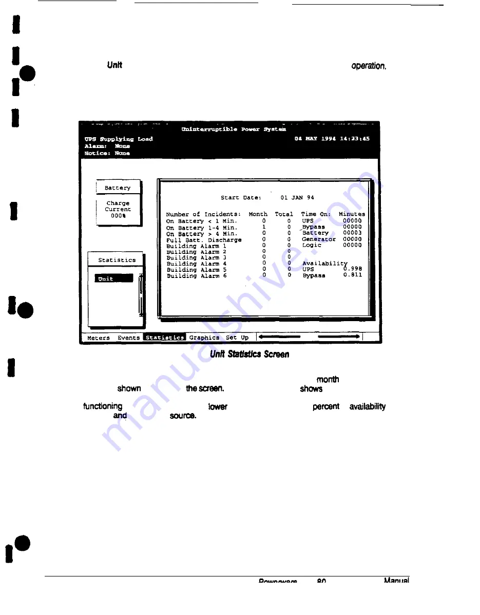
 from the Statistics menu to display a listing of statistics about UPS 

Figure 12 shows the Unil Statistics screen.

Figure 13. 


The left column shows the number of UPS incidents, for the current 

 and since the

start date 

 at the top of 


 The top right column 

 the time that the

UPS was on bypass, battery, or generator, and the amount of time the UPS logic has been

 since the start date. The 

 right column shows the 

 of 

 of

the UPS 

 the bypass 

I

2 6

 Plus 

 UPS Operator’s 

Summary of Contents for Plus 80

Page 1: ...0 Powerware Plus 80 Unintemqtibk Power Supply Operation 164200252 Rev A...

Page 2: ...es Instructions This manual contains important instructions for your Uninterruptible Power Supply UPS system You should follow these Instructions during the installatlon and maintenance d the UPS opti...

Page 3: ...gtheControlPanel To place the UPS in Normal mode To shut down the UPS from Normal mode TostarttheUPSinBypaasmode To shut down power to thecriticaf load while in Bypass mode 3 4 5 6 7 6 9 10 11 12 13 1...

Page 4: ...37 Performing Preventive Maintenance 39 Maintenance Training 39 8 Product Specifications System Input Environmental Specifications Battery Specifications System tput g Responding to System Events Sys...

Page 5: ...ure 6 UPSMonitorPanel 19 Figure9 PartsoftheLCDScreen 20 Figure 10 System Meters Screen 23 Figure11 LoadAmpsMetersScreen 24 Figure12 ActiveSystemEventsScreen I 25 Figure13 UnitStatisticsScreen 26 Figur...

Page 6: ...operation Inpartiwlar you shouldbethoroughly familiarwiththeLoadOffprocedure describedonpage51 Usine This Book This book describes thePowerware Plus 80 UPS andtts operation and routine maintenance lt...

Page 7: ...Communications Describes the RS 485 and RS 232 serial communications capabilities of the UPS system discusses the two communications ports on the Customer Interface Panel inside the UPS and how to co...

Page 8: ...is shipped separately with hardwawfor joining ii to other cabineta during installation As shown in Rgure 1 you can combine a UPS with any of the options described in thii book to customize your syste...

Page 9: ...ows the main elements of the UPS r I BAllERY CABINET AC E r2t I UPS CABINET t AC OUTPUT TFOc6mcAL If utility power is interrupted or tatts outstde the parameters specifed in Chapter 10 the UPS uses a...

Page 10: ...o these contacts alerts you to a UPS afarm This feature is described further on page 32 of Using Features and Options BuildhgAlamIMonitoring You can connect your facffiis alarm system contacts to six...

Page 11: ...r breaker The PD f is enclosed in a separate cabinet that matches the UPS Upgrade Capability The UPS is available in various output power ratings in both 50 and 60 Hz models lf your power requirements...

Page 12: ...rotect personnel fromdangerous voltages inside the unlt l The UPS contains ita own power source Lethal voltages are present even when the UPS Is disconnected from utilitypower WARNING Only AUTHORIZED...

Page 13: ...works with your UPS should understand the meaning of these symbols I 0 A I n f ON The principal power switch is in the On position OFF The principal power switch is in the tIW fmtion PHASE The word p...

Page 14: ...ity power and automatically swftches between these modes as required with no operator imerventfon The sophisticated detection and switching logic inside the UPS ensures that operating mode changes are...

Page 15: ...he UPS is operating in Normal mode PIgum Z Path ot Current Through Um UPS In Nonnal Mode If me utilll AC power is interrupted or is out of speciricatfon the UPS automaticaffy switches to Battery mode...

Page 16: ...gh the UPS In Bypass Mode You can Vender the UPS lrcm Normal mode to Bypass mode manuatiy However the UPS witches automatically to Bypass mode whenever the inverter can no longer supply the uillcal lo...

Page 17: ...ectrical power through the UPS system when it is operating in Sanely mode K4 When the diiarging battery voltage reaches the lower limit of UPS operation capability MeuitkalloadtraMfen to Bypass mode f...

Page 18: ...Ihe left froni of me UPS continually indicate8 me present mode of UPS operation This panel contains an LCD screen backlit status indicators and the Load Ofl button You can use the LCD screen on the Md...

Page 19: ...electrical interconnections to be sure the Installation was successful and the UPS system works properly Using the Control Panel The Control Panel see Figure 7 is inside the right door of the UPS cabi...

Page 20: ...Control on page 51 l The keyawftch activates the power controls on the Control Panel The keyswitch is center biased the key will rest onfy in the upright position its operation is similar to that of...

Page 21: ...UPS in Bvnass mode If the power processing unit PPU of the UPS is not avatlabks and you need to energize your critical load right away you can energtze your critical load without the benekt of backup...

Page 22: ...onitor panel is a black rectangular area on the front of the UPS see Figure 8 1 3 Ffgun a UPS Monthw Panel The monitor panel conteins a flat liquid cryxtal display LCD semen l a horizontal row of push...

Page 23: ...sts me options avaltable on that menu The tttte at the top of the menu box is also shown below on the menu bar E Press me 0 and V pushbuttone to scroll up and down through the options in the menu box...

Page 24: ...hbuttons to move among the menu titles on the menu bar Press them simultaneously to silence the horn or to teat the lamps behind the status indicators l Press the W pushbutton to toggle the usa of the...

Page 25: ...audible horn To silence the horn press the a and 0 pushbuttons simultaneously The Notice indicator may be lit along with other indicators Thtt red symbol is lh when a situation requires immediate att...

Page 26: ...ponents setup Allows you to set up the UPS communications port and set the date and time for the timestamp Figure 10 shows the LCD screen as it appears when you first start the UPS The Meters menu is...

Page 27: ...Meters menu to sea a real time bar graph of the output current of the UPS The graph shows the current for each phase Figure 11 shows the Load Amps Meters screen enase A I 1 1 mast c 24 Powerware Plua...

Page 28: ...tty active The mo 4 recent system event is listed first As events clear they are removed from the Active System Events listing and placed in the Event History Log Figure 12 shows Me Active System Even...

Page 29: ...umn shows the number of UPS incidents for the current month and since the start date shown at the top of the screw The top right column shows the time that the UPS was on bypass battery or generator a...

Page 30: ...ical representation of the flow of current through the UPS Figure 14 shows the Unit Mimic screen Figurn 14 Mlmk Scrwn The Mimic screen shows the internal components of the UPS cabinet The flow of curr...

Page 31: ...w W appears in the upper right comer of the information area of the Event History Log screen This arrow is a reminder that you can press the 9 pushbutton on the Monitor Panel to toggle the scroll bar...

Page 32: ...e information area When the scroll bar is in the informatlon area the return arrow ls in the menu box When the scroll bar is in the menu box me return armw is in me inforrnatfon area When the scroll b...

Page 33: ...ea When me scroll bar is in me information the return arrow is in the menu box When me scroll bar is in me menu box me return armw is in me information area When me scroll bar appears in me informatio...

Page 34: ...CH RAE0 AT 24 VDC i OMA MINIMUM CONNECTED BETWEENTHE ALARMINPUTTERMINALANDCOMMON lERMlNA4 AS SHOWN ALL CONIROL WIRINQ AND RELAY ANDSWllCH COh TACl SARE CUsrOMER PROUDED M 18 Externaf CannecUorts for B...

Page 35: ...are located inside the UPS on the customer interface panel see Figure 19 lB2 NOTICE NC 1 0 0 NOTICE NO 11 0 COMMON 12 0 _ _ _ _ _ ALARM NC 130 ALARM NO 1 4 0 COMMON 150 _ _ Flgure 19 Summary Alarm Con...

Page 36: ...he UPS and the RMP is not present the RMP will setf teat all indicators Rash and the horn beeps at one second intervals lf this occurs check all harness connectors and the fuse for proper seating if a...

Page 37: ...ARM The UPS system is issuing an alarm Cofldiions that effeci the curreni UPS mode are indicated by the alarm lamps and horn on the UPS The following conditions do not immediately affect the current m...

Page 38: ...mitations your battery cabinets may not be located in the same area as your UPS An optional external DC circuit breaker provides a manual means of disconnecting a battery that is located remotely from...

Page 39: ...available BATTERY WEAK connector pins 5 and 14 Relay 3 is energized indicating that shutdown is imminent The UPS has approximately 2 minutes of battery time remaining until it will no longer support...

Page 40: ...nnel should wait at least 5 minutes before attempting internal access to the UPS system j DANGER LETHAL VOLTAGE PRESENT Thla unit should not be oparatad with the Icabinet doom open or protactlva panel...

Page 41: ...e number of sealed lead acid batteries l Proper disposal of batteries is required Refer to your local codes for disposal requirements jCAUTION HAZARDOUS WASTE Do not incinerate or dispose of batteries...

Page 42: ...neously to test the lamps l Monitor system pammaters as described in Using the Monitoring Panel on page 19 l Check the air fitters located behind the front doors and replace them as neceswy Thefilters...

Page 43: ...cations for this UPS System Input 3pereUng lnpul Voltage 50 Hz Models 400 VAC for operation from 318VAC to455VAC Suitable for use on 35OV 4OOV and 415V systems 208 VAC for operation from 177 VAC to 22...

Page 44: ...s up to 25 kV without damage and with no disturbance or adverse effect to the critical load System Efttclency at Full Unity Power Factor Load and Nomlnal Input Voltage 0 Hz Models Note The 208 systems...

Page 45: ...ltage Harmonk Content 3 max THO 2 max single for linear load htput Voltage Balance 2 for 100 maximum load imbatance Wtput Voltage Pheee 2 for 100 maximum load imbalance Xeplacement htput Tranalente 25...

Page 46: ...PS detects an alarm that requires your attention the horn beeps at V second intervals l When a notice occurs the horn beeps at Z second intervats l If the battery contactor is open and the Bypass is u...

Page 47: ...nverter AC Under Voltage lnverter Over Frequency Clear lnverfer Over Frequency lnverter Under Frequency Clear lnverter Undar Frequency Over Temperature Shutdown 100 Overload Shutdown 125 Overload Shut...

Page 48: ...ered to Bypass Inverter Messages Commands Bypass Mode Nonal Mode Keyswitch On lnverter Commanded On lnverter Commanded Ofl Inverter Status Messages lnverter On lnverter Off sanely contactor K2 closed...

Page 49: ...ilure Rectifier Failure Rectifier Alarm Rectifier Messages Notices Input AC Over Voltage Clear Input AC Over Voltage Input AC Under Voltage Clear Input AC Under Voltage Input AC Over Frequency Clear I...

Page 50: ...e Clear Power Supply Fail Fen Failure Clear Fan Failure Monitor Panel Notices Output AC Over Voltage Clear Output AC Over Voltage Output AC Under Vol w Clear Output AC Under Voltage OulpuI Over Freq C...

Page 51: ...Alarm 2 Building Alarm 3 Clear Building Alarm 3 Building Alarm 4 Clear Building Alarm 4 Building Alarm 5 Clear Building Alerm 5 Building Alarm 6 Clear Building Alarm 6 Rectller Network Down Rectitier...

Page 52: ...the Load Off button 1 Raise me clear piaatic shield covering the red LOad Off button on me monitor pSUlel 2 Press me Load Off button me breaker and wntactors open you can hear them opening The CBl sw...

Page 53: ...features and options of the UPS battery cabinets 36 building atann monitoring 31 external battery disconnect 36 relay interface module 36 remote monitor panels 33 summary alarm contacts 32 H horns re...

Page 54: ...responding to 45 system input specification s 41 System Meters screen 23 system output specifications 43 T temperature specifications 42 Time Setup screen 29 timestamp of the UPS setting 29 training c...

Page 55: ...a 1 a Pe WNP U N I N T E R R U P T I B L E P O W E R S Y S T E M S I i b I EXlDE ELECTRONICS...

Page 56: ...I I I a I I I I I I IO I I I I I I I Powerware Plus 80 Uninterruptible Power Supply Comlnunication 164200254 Rev A 1 For Field Service Call I 800 84MIDE 1...

Page 57: ...Instructions This manual contains important instructions for your Uninterruptible Power Supply UPS system You should tallow these instructions during the installation and maintenance of the UPS option...

Page 58: ...ial Ports 6 Mode 7 Rate 7 Data Stop a Handshaking a Disabled No Handshaking a XONiXOFF a Save a DefaunSettings a 3 Using Communications Modes 9 Print All Mode 9 PrintingS8lected Information 10 Entire...

Page 59: ...ommunications Ports on the UPS 3 Figure 2 Port 1 Pin Assignments 4 Figure 3 Port 2 Pin Assignments 5 Figure 4 Setup Serial Port 1 Screen 6 Figure 5 Event History Log Screen 10 Figure 6 System Meters S...

Page 60: ...r operattonaf concerns In this book the term UPS refers only to the UPS cabinet and its internal elements The term UPS system refers to your entire power protection system the UPS cabinet plus any opt...

Page 61: ...ormation in this book or if you have a question this book does not answer please call Customer Support I United States l 800 843 9433 1 80044EXIDE I Outside the U S Call your local representatlve I I...

Page 62: ...contains two output breaker panelboards Tel and T82 for connecting your equipment to the UPS Figure 1 shows the location of these items inside the UPS PORT 1 DE 9 EYi TBl and TB2 CUSTOMER F2E po vg2...

Page 63: ...ut configuration The cables you use for connection depend on the equipment you are connecting to the UPS Cables should be no longer than m SO fl The connectors for Port 1 and Port 2 on the customer in...

Page 64: ...nd I lnrwt to UPS 5 CTS Clear to Send Output from UPS 6 1 D S R IDataSetReady I Outwt from UPS 7 7 RTN RTN Return Return a a 12v 12v 12volts 12volts 1 Output from UPS always true Output from UPS alway...

Page 65: ...ahow p appears in the upper right comer of the Port Setup screen This arrow is a reminder that you can press the pushbutton on the Monitoring Panel to toggle me pushbuttons between the menu box and th...

Page 66: ...yet implemented Computer Allows you to use Binary Computer Mode BCM Not yet implemented Remote Monitor Sends all system event information to a remote monitor panel RMP Available for Port 1 only Port...

Page 67: ...ial port ignoring all inputs from handshaking lines XONIXOF F If handshaking is enabled the UPS uses special characters Xon and Xoff to handshake with the host terminal The Xon character is defined to...

Page 68: ...ode In this mode system events are continually logged through the serial port to whatever device is connected to the port For example if the port is connected to a printer events print immediately as...

Page 69: ...with the most recent event listed last Figure 5 shows a sample Event History Log printout Uninterruptible Power System UPS supplying Load 03 JAN 1994 14 22 49 Alarm NOTiCS Notice None Event History L...

Page 70: ...22 4 3 Alarm NOIE Notice NOIEZ Input output VAB VBC VCA FREQ AB VBC VCA FREQ 4 8 0 4 8 0 480 60 0 208 208 208 60 0 IC 0 0 080 KVA W PF WA Kh PF 080 076 0 80 076 0880 80 I This key sequence prints a li...

Page 71: ...the UPS The RMP contains a local horn and these backlit status indicators SYSTEM NORMAL NOREDUNDANCY ON GENERATOR ON BYPASS UPS ALARM ON BAlTERY BYPASS UNAVAILABLE SHUTDOWN IMMINENT The relay interfac...

Page 72: ...I I I I I I U N I N T E 4 f RRUPTIB Z a L E P O W E R SYSTEMS P 10 I I I I I I I L INS I HIDE fLECTRONICS...

Page 73: ...5 3 6 3 7 3 8 3 3 4 0 41 4 2 4 3 0 100 1 0 0 1 t 12 5 100 1 00 4036 0 0 0 43605 43605 0 0 za19 0 0 4 0 6666 17500 13 2817 6000 100 2819 1286 100 8 8 1011 0 1286 3000 43605 128 1000 2 920 3 500 2820 45...

Page 74: ...0 7 7 0 7 8 0 7 9 0 ao 1200 ai 10500 8 2 10000 a 3 9 5 0 0 a 4 12OOOJ a 5 8000 8 6 6 0 0 a 7 2570 88 500 a 9 2 0 0 0 9 0 1433 31 1739 9 2 139 3 3 2 2 5 9 4 2 5 9 5 120 3 6 0 9 7 0 1 o ou 0 1oooo 0 1 o...

Page 75: ...I I I 101 2 0 0 102 a 103 6 4 0 I 104105 12025 106 0 I 107108 8360 0 103 0 I 1 1 111 0 4650 0 112 0 113 4 8 0 0 I Jdw I 4500 8000 10000 830 0 0 0 0 0 0 0 0 0 0 0 0 0...

Page 76: ...l I b l b I 4 Powerwar Plus 80 Uninterruptible Power Supply Installation 164200253 Rev I3 1 for field Service Call I 800 84MIDE 1...

Page 77: ...ver CesInstructions This manual contains important instructions for your Uninterruptible Power Supply UPS system You should tallow these instruotionsduring the installation and maintenance of the UPS...

Page 78: ...nets Preparing the UPS for Installing Optional Cabinets or Accessories 11 13 14 17 19 4 Joining Cabinets Joining an Optional Cabinet to the UPS Method A Joining Optional Cabinets to Each Other Method...

Page 79: ...odule 8 lnstalllng a Remote EPO Control 9 Installing a Remote Battery Disconnect 70 lnstalllng a Remote Monitor Panel 17 Installing a Relay Interface Module 12 Appendix Customer Information 10 I I I I...

Page 80: ...e UPS system that includes at least one of each component I PDM CABINET INPUT UPS BATTERY optiona Y ZRmMER CABINET CABINET optional optional Flgun 1 Sample UPS Sy 3tem IJ I w1 BArrERY CABINET optional...

Page 81: ...Module PDM Chapter 6 Remote Monitor Panel RMP Chapter 9 Remote Interface Module RIM Chapter 10 Remote Emergency Power Off EPO control Chapter 11 Remote battery disconnect l The Appendix contains impor...

Page 82: ...l Communications Describes the M 485 and FE 232 serial communications capabilities of the UPS system discusses the two communications ports on the Customer Interface Panel inside the UPS and how to co...

Page 83: ...ogether Chapters 6 10 as applicable 6 Install features accessories and or options Chapters 6 10 as applicable 7 Complete the Installation Checklist on page 9 8 Authorized service personnel perform pre...

Page 84: ...cabinets use convection cooling to regulate internal component temperature Air inlets are in the front of the cabinet and outtets are in the top You must allow clearance in front Of and above each cab...

Page 85: ...Pa t 1 Carefully inspect the outer packaging for evidence of damage during transl CAUTION i Do not fnetella damaged cabinet Report any damage to the carrier and contact your local ealea or eervlce off...

Page 86: ...Use the procedures and illustrations in the following sections to create a logical plan for installing the UPS and optional components you purchased The information in Chapter 3 will help you plan you...

Page 87: ...etc 0 Air conditioning equipment is installed and operating correctly Q The area around the instatfed UPS system is clean and dust free It is recommended that the UPS be installed on a sealed concret...

Page 88: ...I I I I I I IO I I I I b I I NOTES 10 Powemam Plus 60 UPS ln stallation Manual...

Page 89: ...he UPS cabinet arrives as shown in Figure 3 below COOUN G7 AIR INLETS COOLING AIR EXHAUST TOP lllllillllllllll 1111111111111111 1111111111111111 llllllllllllllll 1111111111111111 1111111111111111 1111...

Page 90: ...to theterminals l The remote Emergency LoadCff feature opens all breakers andcontactors in the UPS cabinet and isolates power from yourcritical load Local ectncai codes may also require tripping upstr...

Page 91: ...six bolts joining the front support to the cabinet e ______ SIDE SUPPORT FROh IT SUPPORT I 6 FOAM Ffgura 4 f enmvfng Font and Rear Supports 2 Remove the rear support in the same way you removed the fr...

Page 92: ...ts of a rectangular metal frame holding three casters The caster assemblies should be installed in the two forklii openings on the bottom of the cabinet The nuts and lo washers for bolting the caster...

Page 93: ...de it at an angle into one of the forklift openings on the bottom of the cabinet Each caster assembly fits on four studs two at the front and two at the back on the bottom of the cabinet see Figure 7...

Page 94: ...ng the Caster Assembly to me Cab net 6 Place one lockwasher on each stud then screw one nut onto each stud lighten the nuts securely torque to 25 nM 19 4 lb 6 Repeat steps 3 through 5 for the other ca...

Page 95: ...1 Remove the right cosmetic cover and the right side panel of the UPS and set them aside for future use 2 Open the doors of the UPS 3 Remove the lower safety shield Set the safety shield and hardware...

Page 96: ...I I I I I RIGHT SIDE PANEL SIDE PANEL MOUNlING SCREWS LEVELING FE Ci BAlTERY CABLE LEFT SIDE PANEL RIGHT SIDE PANEL PIgun 10 Prepaffng me UPS lbr lmtallfng other cabheta RIGHT DOOP I 18 p0 3fware Plus...

Page 97: ...ned off and all power sources are removed See the Operator s Manual for instructions 2 Remove the left side panel of the UPS and set it aside 3 Open the doors of the UPS 4 Remove the safety shield loc...

Page 98: ...he sides of all cabinets except the outermost right and left cabinets of a lineupand match system Do not remove the cosmetic covers from the sides of stand afone cabinets I i FE 2 EN lERY C4BLVEf PDMU...

Page 99: ...t should be joined to the left side of the UPS A battery cabinet should be joined to the right side of the UPS C ____ ___ Ffgum 12 Joining an Optional Cabinet to the UPS 3 Remove the cosmetic covers f...

Page 100: ...the cabinet bottoms To join an optional cabinet to the left side of the UPS use the same procedure but use the leti angle bracket Remove the screw from the top door hinge of each cabinet Align the ho...

Page 101: ...page 24 L o w e r door hinge Ffgwe 16 lnsfafhg fhe A n g l e d Emcket 9 Insert the tab B into the slot in the base of the optional cabinet 10 Slide the bracket toward the UPS cabinet while slipping t...

Page 102: ...F gum 16 Preparfng to Joln Componeni Cabheia 4 Push cabinet 2 from the front until both cabinets are aligned at the rear as shown in Figure 17 This action will seat the rear joining clamps as shown i...

Page 103: ...d i atleif I I I Flguru I Cabinet toCabinet Gmundlng 2 Mount the ground bus provided as shown in Figure18 and secure 1 to the frame of each cabinet using the nuts you removed in step 1 3 Be sure each...

Page 104: ...l objects l Use tools wlth insulated handles l Wear rubber gloves and boots l 00 not lay tools or metal parts on top of batteries or battery cabinets l Disconnect the charging source prior to connecti...

Page 105: ...al is 11 gauge steel I20 inchesthick l Control wiring must be installed in separate conduit from the power wiring l Each battery cabinet can be installed as a stand alone unit or as part of a redundan...

Page 106: ...Type 1 battery cabinet arrives as shown in Figure 19 TOP VIEW STUDS FOR GROUNDING LUG SWIVEL RMIll 9 PICAL SoTrOM VIEW 3 a JOINING POINTS or joining to other cabinets See Figure 17 on page 25 c Power...

Page 107: ...CTION AND SUBSEQUENT SECTIONS 5 Remove the center deadfront and battery drawer connector guard see Figure 20 retaining them and their hardware for later reuse 6 ff you are installing more than one bat...

Page 108: ...a lype 1 talteiy CabfIlet _ CENTER DEADFRONT WITH MOUNTING SCREWS AND MOUNTING NUTS A RIGHT TOP DEADFRONT WITH MOUNTING SCREWS i EATERY BREAKER BA KERY DRAWER CONNECTOR GUARD BATTERY DRAWER CONNECTOR...

Page 109: ...string connectors m right side panel removed in step 1 of To prepare the battery A I to the right side of the end battery cabinet 8 Mount the hanger bracket to the top right side of the battery cabine...

Page 110: ...d E5 and tiewrapped in place Remove the screws thatsecuretheleftcableconnector andremovethetiewrapapsecuring theleft wireplug SeeFigure20forconnectorandpluglocations 2 Mate the left cable connector an...

Page 111: ...cabinet as it arrives with the doors closed See Drawing 164200263 7 on page A l 6 for cabinet dimensions IO I I I I I I I I0 JOININGPOINTS for joining to other cabinets SeeFigure17 on page 25 7 1 JOI...

Page 112: ...EMAINING STEPS IN THISSECllON AND SUBSEQUENT SECTIONS 3 R8mOVe th8 center deadfront Retain it and its hardware for later reuse 4 lf you ar8 installing more than one battery cabinet perform steps 1 thr...

Page 113: ...PANEL LEVELING FEET STRING CONNECTORS behind center deadfront EATERY BREAKER DEADFRONT LEFT CABLE SA I ERY DRAWER CONNECTOR CONNECTORS _ RIGHT CABLE CONNECTOR FIglIfe 22 wrfhlg qpe 2 battery cabllmta...

Page 114: ...ion 4 See Figure 3 on page 11 to locate TB3 in the UPS cabinet If TB3 is supplied connect two control wires to it and route the wires through the battery cabinet top or bottom entry toTBI See Table L...

Page 115: ...nected to terminals E4 and E5 and tlewrapped in place Remove the screws that secure the left cableconnector and remove thetiewrap securing the left wire plug s 2 Mate the left cable connector and the...

Page 116: ...e 19 The input transformer cabinet arrives as shown in Figure 23 See Drawing 184200253 8 on page A 18 for cabinet dimensions or joining to other cabinets JOINING POINTS See Figure 17 on page 25 I JOIN...

Page 117: ...t frames using the procedure on page 26 7 Securethe cabinet wfth its leveling feet To wire the input transformer cabinet to the UPS 1 Cables for interconnecting the input transformer to the UPS are co...

Page 118: ...JOINING POINTS See Figure 17 on page 25 J x J 3 1111111111 AC INPUT TO UPS INPUT TRANSFORMER CONNECTIONS LEVELING FEET Flgure 24 lnata lhg an Input Rmfomnw Cabinet Powerware Plus 80 UPS installation M...

Page 119: ...PDM cabinet arrives as shown in Drawing 1942W253 9 on page A 19 and Figure 25 below Before installing the PDM be sure you have prepared the UPS according to the instructions on page 19 1 1111111111111...

Page 120: ...eentheframesoftheUPSandPDMcabinet using the procedure on page 26 6 Secure the PDM cabinet with its front leveling feet To wfre the PDM cabinet to the UPS 1 Cables for interconnecting thePDM totheUPSar...

Page 121: ...left side cover at the bottom with screws 5 Replace the deadfront on the UPS cabinet Close the UPS and PDM cabinet doors If you would like to buy additional breakers see Table D for descriptions of th...

Page 122: ...te EPO station Recommended locations include operator s consoles or exit doors 2 lnstafl wiring from the Remote EPO station through I 2 conduit and through the l 2 knockout in either the top or the bo...

Page 123: ...s wire additional stations in parallel with the first Remote EPO I 5 If required install l 2 conduit and wiring from the Remote EPO station to trip circuitry of upstream protective devices A normally...

Page 124: ...DC supply and the UPS according to national and local codes Figure 27 shows the remote battery disconnect enclosure as it arrives SIDE 1 0 FRONT ON u OFF Flgum 27 Remote BetMy Disconnect Enclo8um The...

Page 125: ...UPS to battery cable should be sized for a total maximum voltage drop of 1 nominal DC link voltage at maximum current l The external wiring specifications are outlined in Table G on page 51 Tables H a...

Page 126: ...larms Remote Monitor I and Remote EPO Amps 1 1 1 1 1 111 1 1 I Table H Remote Battery Disconnect Power Terminations I Terminal E4 I E5 Size of Pres sufw Termination 1 8 3 O 1 S 3 0 Terminal Function U...

Page 127: ...f 7 I cc UNK BA ERY I DISCONNECT TO BATTERY I DC UNK I I I UPS TO I YNECT l I BAlTERY B 105 l 20 CELLS 21 o 240 VDC I I I I I L J I BAl fERY OlSCONNEC rl L J CONNECTION FOR REMOTE STAND ALONE BAlTERY...

Page 128: ...RMP on a desk3op or on a well wherever you have a serial interface line Figure 29 shows an FM Drawing 164200253 12 on page A 22 shows the enclosure dimensions and knockout patterns r I I I I 1 I 7 r...

Page 129: ...allation of l 2 flexible conduit within the UPS Bottom entry connection requires no additional routing of conduit within the UPS 3 In the hardware kit locate the terminal block bracket see Figure 39 C...

Page 130: ...S PER lWlSTED WIRES 4 l 2 TURNS PER 5 To check the operation of the RMR ensure that the UPS is supplying the load via inverter or bypass If the indicators on the RMP show the appropriate status then t...

Page 131: ...vice office for verification that the RMP is working correctly 6 To test the indicator lamps press the horn silence button and hold it for 3 seconds All lamps should light and the horn will sound cont...

Page 132: ...e To install an RIM 1 Securely mount the RIM 2 Install wiring from the RIM through l 2 conduit and through the l 2 knockout in either the top or the bottom of the UPS cabinet The top entry connection...

Page 133: ...I0 I Connect to Port 1 DE i 9 on Customer Interface Panel FUSE Ffgum 33 Tenninaf 13lock Bracket DE 9 CONNECTOR ON COMMUNICATIONS PANEL OF THE UPS Ffgum 34 Wfrfng an RIM to the UPS ERMINAL BLOCK Powem...

Page 134: ...INCHES I Ted 7 TB3 8 5 Contact your local field service office for verification and testing of the RIM and its connections prior to making connections with Jl J4 You can order interface cables separat...

Page 135: ...s of UPS System 164200253 4 Location o UPS Power Terminals 164200253 5 UPS Cabinet 164200253 6 915 mm Battery Cabinet 164200253 7 610 mm Battery Cabinet 164200253 6 Input Transformer Cabinet 164200253...

Page 136: ...necessary Table L Ratings 8 External Wiring ReqUirsmsnts Ratings Uniis 1 Rating 60 HZ 66 52 I Bsslc unit rating at 0 6 la n9 PF load 206 600 206 206 480 208 91 23 114 l O 1 96 d 180 160 7 222 300 1 l...

Page 137: ...lllers sec 1300 cfm 9 Battery voltage is computed at 2 volts per cell as defined by article 480 of the NEC Rated battery current is computed at 1 8 volta per cell 10 The battew wiring used between the...

Page 138: ...iring Terminations Teminal TSl Description Terminal Block Terminal Function Building Alarms optional up to 3 Generator Interface TSl TB2 TB2 Terminal Block Table 0 Summary Alarm Relay Contacts 14 0 NO...

Page 139: ...plying a 150 kVA three phase transformer to allow for transformer magnetization inNsh current d The input breaker CM has atrip rating of150 Amps AT and an Amp interruptingcapabiiii AIC of 25 ooO in sy...

Page 140: ...ion panel in the PDM has 84 poles 22 The PDM cabinet is bottom entry only 23 Terminals El through El5 are UL and CSA rated at SO C A hex key tool is required to attach wires to terminals Refer to Tabl...

Page 141: ...ent s operating environment must meet the size and weight requirements shown in Table S according t0 your UPS system configuration 26 The basic environmental requirements for operation of the UPS syst...

Page 142: ...N sAMpLE urn sysTul DRAWING NO 164200253 2 SHEET 1 of cRE47Eom L ORuNoo FTEwsIOw A j OAlE 2 g P L Y 4 C A B I N E T I N P U T U P S BAnmY optional w TNREMER CABINET CABINET BTNZ QPUow optional OPtiona...

Page 143: ...RFACE PANEL I 1 INPUT TRANSFORYER j PDMCABINET C A B I N E T I oPnowO UPS CABINET ____ _L __ L cTO GROUND UPS SYSTEM WITH OPTIONAL INPUT TRANSFORMER oEscRlpTloNr ONELINE DRAWINGS OF UPS SYSTEM DRAWING...

Page 144: ...C d m P pages A 4 Vough A B J UWdO 1 ROTATION cm INTERFACE PANEL PDY CASINt 0 UPS CABINET 1TO GROUND UPS SYSTEM WITHOUT OPTIONAL INPUT TRANSFORMER DE m ONELINE DRAWING 3 OF UPS SYSlEl ORAWING NO 1642a...

Page 145: ...T C I I I 1 I Id ES mmt MlON OF UPS POWER TERMINAL DR W NG NO 1642cO253 4 SHEET o aiEAE0 m L oww flEvlsioN A OATE a 94 I A 11...

Page 146: ...1111111111111111 llllllllllllllll 1111111111111111 llllllllllllllll A 12 Pawemare Plus 80 UPS hstallation Manual...

Page 147: ...2 I FRONT Powerware Plus 80 UPS installation Manual A 13...

Page 148: ...i I A i 436 0 17 13 I 1626 6 64 13 cl 0 v 11111111111111111111111111111111111111 llllllllllllllllllllllllllllllllllllll 0 DEsOR moN TYPE 1 SAlTERY CABINET 610 mm DRAWING NO 164200263 8 aEArED m L ORUN...

Page 149: ...79 142 3 5 W 637 4 25 09 I I 624 9 24 60 x 90 DEGREE OOOR SWlNG FOR SUBASSEMBLY REMOVAL I 8 t 219 1 6 W TOP CABLE p I e I 226 6 I I SCREWS i _ __ L m cR pnoN TYPE 1 BAll ERY CABINET 610 mm DRAWING No...

Page 150: ...I I I I I I I I I I I 914 4 I 36 00 ia 0 I LEVELING FEET DEscRIpTK N lWE 2 SAHERY CABINET 915 mm m4mNG No 1642oo253 7 1 WErn o cFEAlEo m L omJNoo 1m3lswM j OAm 8 2 g A 16 Powwware Plus 60 UPS Install...

Page 151: ...6 9 3so D MlvEL RAOIUS FW n TYPE 2 BATTERY CABINET TOP VIEW TOP CABLEENTRY LOCAllON COVER SECUREDw TH FOUR SCREWS 660 5 26 79 l 142 7 5 62 WAIL NO SACK ACCESS RECUIREO 0 GROUNDINGLUG DESOR TYPE 2 BAl...

Page 152: ...mON INhJl TRANSFORMER CASINR ORAwfffi No 164200253 6 iSfEET 1 o CREATE0 811 L 0RuN00 REvrsIoN A j 0Al E 2 609 6 24 00 lllllllllllllllllllllllllllllllllll lllllllllllllllllllllllllllllllllll z a a a a...

Page 153: ...5 61 CRE47Eo By L ORLANDO RMWON A ONE B 269r Powemare Plus 90 UPS lnstailation Manual A 19...

Page 154: ...I I I I I 115 8 4 56 Knockoul pattern iyp 5 sides TO UPS TOOTHER EQUIPMENT XIU REMOTE EMERGENCY POWER OFF OR4WlNG NO 1642 3253 10 s Em 1 of 1 EATEo m L ORlANoa RMSIOW A LwE 6 24 94 A 20 Powerware Plus...

Page 155: ...8 7 P 7 328 8 3 DIAMEIER HOLES 4x 698 01 273 OEscRIpIIoN REMOTE SMlERY DISCONNECT OR4WlNG NO l Qfj 53 11 s Em 1 o f CRGllED m LORLANDO Fm sGM A j DvE 8 24 i Powemam Plus 80 UPS Installation Manual A 2...

Page 156: ...SIZE NO 18 AWG SURFACE MCUN FOR HANGING I I CONDUIT AND WIRING SUPPLIED EM q yty CUSTOMER MAX DISTANCE BETWEEN REMOTE MONITOR AND UPS NOT TO EXCEED 500 FEET oESCXpTK N REMOTE MONITOR PANEL ORAWWG No 1...

Page 157: ...19 0 FLUSH MOUNT 750 I A t 00 00 iI I F 190 5 7 50 Relay Interface Module DEScX p RELAY INTERFACE MODULE 33 _...

Page 158: ...jr ilol m 1 I 273 1 10 75 215 9 171 5 6 W 6 75 KNOCKOUTS PROVIDED ON FIVE SIDES DEscR RELAY INlERFACE MODULE DRAWlNO NO 164200253 13 SHEET 2of cRE4rEo m L ORlANno RE S ON A ME 6 24 3 A 24 Powerware Pl...

Page 159: ...flatfon notes 26 joining to other battery cabinets 21 26 joining to me UPS 21 22 preparing the UPS cabinet 17 tilting 26 bold lype used in this book 2 C cabinet to cabinet grounding 26 cabinets damage...

Page 160: ...wiring requirements 51 illustratton 49 installation notes 50 knockout pattern 50 remote EPO illustration 47 installation 47 installation note A 7 preparing the UPS cabinet for 19 wire terminations 47...

Reviews: