


13.0 Changing Components
34
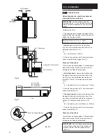
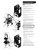
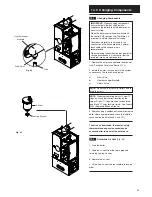
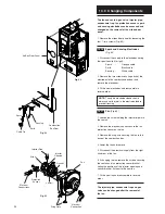
The fan and venturi, gas valve, injector pipe,
condensate trap, fan protection sensor, spark
and sensing electrodes can be accessed and
changed on the removal of the airbox door
panel.
1. Remove the airbox door panel by loosening the
four
1
/
4
turn screws (Fig. 63).
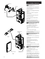
13.16
Spark and Sensing Electrodes
(Fig. 64)
1. Disconnect the supply to the electrodes noting
their positions (left to right):
Spark
-
Opaque cable
Earth
-
Black cable
Sensing -
White cable
2. Remove the two screws securing each of the
electrodes to the combustion box door and
remove the electrodes.
3. Fit the new electrodes and reassemble in
reverse order.
NOTE
: The spark electrode sleeve should
always cover the joint in the electrode lead to
prevent tracking.
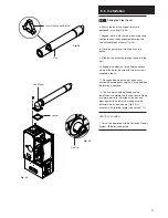
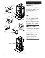
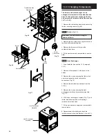
13.17
Fan
(Fig. 65)
1. Loosen the screw holding the injector pipe into
the venturi.
2. Remove the electrical connections to the fan
protection sensor on the fan.
3. Remove the wing nuts securing the fan to the
base of the combustion box.
4. Lower the fan and remove.
5. Disconnect the electrical supply from the right
hand rear of the fan.
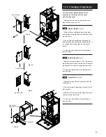
6. If changing the fan remove the screws securing
the venturi and fan protection sensor bracket,
noting the positions of the injector opening and
sensor bracket, fix them to the new fan.
7. Fit the new fan and reassemble in reverse
order.
The injector pipe, condensate trap and gas
valve can be changed after the removal of
the fan.
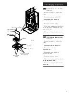
Wing Nuts
Injector Pipe
Screw
Electrical
Connections
Electrical
Connection
Protection
Sensor
Injector
Opening
Gasket
Venturi
Fan
Sensing
Earth
Spark
Combustion
Box Door
Fig. 63
Fig. 63
Fig. 65
Air Box Door Panel
Cable Tie


