2.0 General Layout
5
2.1
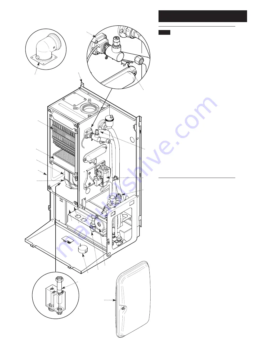
Layout
(Figs. 3,4 & 5)
1.
Wall Plate
2.
Flue Elbow
3.
Heat Exchanger
4.
Burner
5.
Air Box
6.
Fan Protection Thermostat
7.
Fan Assembly
8.
Condensate Trap
9.
Gas Tap
10.
Gas / Air Ratio Valve
11.
Electronics Housing
12.
Transformer
13.
Flow Temperature Safety Thermostat - Black
14.
Flow Temperature Thermistor - Red
15.
Flow Switch (dry fire protection)
16.
Circulation Pump
17.
Automatic Air Vent
18.
Pressure Relief Valve
19.
Water Pressure Gauge
20.
Expansion Vessel
1
2
3
4
5
6
7
8
9
10
11
12
13/14
17
16
Fig. 4
Fig. 3
Fig. 5
15
18
19
20
Fig. 6


