


8.0 Installation
17
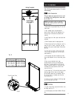
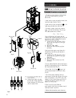
Wall Thickness
up to 227mm
up to 750mm
up to 1200mm
Flue Hole ø
125mm core drill
150mm core drill
175mm core drill
Check Site Requirements (section 7.0) before
commencing.
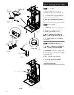
8.1
Initial Preparation
The gas supply, gas type and pressure must
be checked for suitability before connection
(see Section 7.6).
NOTE:
If the boiler is to be pre-plumbed,
follow both these instructions and those on
the boiler pack.
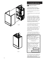
1. Remove the fixing template (Fig. 20) from the
fixing carton.
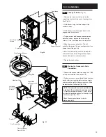
2. After considering the site requirements
(see Section 7.0) position the template on the
wall ensuring it is level both horizontally and
vertically.
3. Mark the position of the top centre hole for the
wallplate.
4. Mark the condensate discharge pipe area.
5. Mark the centre of the flue hole (rear exit). For
side exit, mark as shown. If required, mark the
position of the gas and water pipes. Remove the
template.
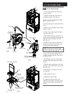
6. Cut the hole for the flue (minimum diameter
125mm) (see table opposite for wall thickness
flue diameter’s).
7. Drill and plug the wall as previously marked.
Secure the wallplate to the wall by the top centre
hole.
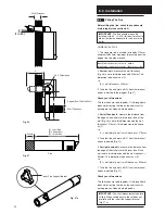
8. Ensuring the wallplate is level both
horizontally and vertically, drill and plug the
remaining 4 securing positions at the top and
bottom through the wallplate. Utilising the slots
available ensure the wallplate is square and
secure to the wall.
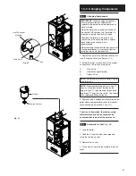
9. Connect the gas, water and the pressure relief
discharge pipes to the valves on the support
bracket using the copper tails supplied. Ensure
the sealing washers are fitted correctly to the
water connections.
10. Loosely route the condensate discharge pipe
to the area previously marked.
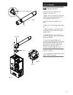
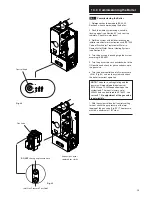
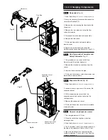
8.2
Flushing
1. Insert a tube into the valve outlet furthest from
the filling loop (Fig. 21).
2. Flush thoroughly (see System Details, Section
6.0).
Fig. 20
Plastic Flushing Tube
MINIMUM CLEARANCE 5mm EACH SIDE
37mm
ELECTRICAL SUPPLY
GENERAL AREA FOR
CENTRE LINE OF FLUE AT 3 DEGREES
CENTRE LINE OF FL
UE AT 3 DEGREES
TO 750mm (30")
WALL THICKNESS UPTO 227mm (9")
CENTRE FOR DIA.150mm (6") HOLE
WALL THICKNESS UPTO 227mm (9")
CENTRE FOR DIA. 125mm (5") HOLE
WALL THICKNESS UPTO 227mm (9")
CENTRE FOR DIA. 125mm (5") HOLE
NOTE : FOR EACH 1m OF HORIZONTAL FLUE ADD 55mm OF CLEARANCE ABOVE THIS LINE
APPLIANCE OUTLINE
PROMAX SYSTEM HE
BOILER
FIXING TEMPLATE PART No. 5106702p
FLOW
RETURN
DRAIN
CONDENSATE
SUPPLY
GAS
RELIEF
PRESSURE
BOILER CENTRE LINE
Fixing Template
Fig. 21


