background image

8.0 Installation

21

8.6

Fitting the Flue (Cont)

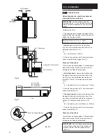
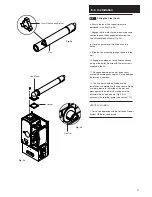
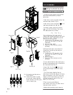
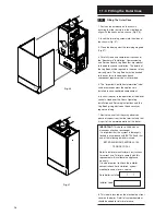
6. Ensure the inner flue support bracket is

positioned in the flue (Fig. 28).

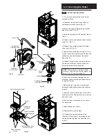
7. Engage the flue into the flue elbow using soap

solution to ease the engagement ensuring the

flue is assembled as shown (Fig. 29).

8. Place the gasket over the flue exit on the

boiler.

9. Slide the flue assembly through the hole in the

wall.

10. Engage the elbow on to the flue connection

on top of the boiler. Secure with the four screws

supplied in the kit.

11. Make good between the wall and air duct

outside the building ensuring the 3° drop between

the terminal and elbow.

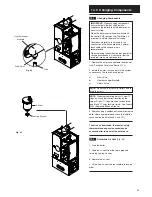
12. The flue trim should be fitted once the

installation is complete and the flue secure. Apply

a suitable mastic to the inside of the trim and

press against the wall finish, making sure the

brickwork is dust free and dry (Fig. 30). If

necessary fit a terminal guard (see section 7.11).

VERTICAL FLUEING

1. Only a flue approved with the Potterton Promax

System HE Boiler can be used.

Gasket

Flue Trim

Inner Flue Support Bracket

Flue

Flue Elbow

Fig. 28

Fig. 30

Fig. 29

Summary of Contents for Promax System HE

Page 1: ...Installation and Servicing Instructions Please leave these instructions with the user Promax System HE Wall Mounted Powered Flue Condensing Boiler Gas Fired Central Heating Unit ...

Page 2: ... paid guarantee registration This does not in any way prejudice your rights at Common Law Such rights between the customer and the installer or supplier from whom the unit was purchased remain intact Any component or part which becomes defective during the guarantee period as a result of faulty workmanship or material whilst in normal use will be repaired or replaced free of charge B S Codes of Pr...

Page 3: ...mensions and Fixings 8 6 0 System Details 9 7 0 Site Requirements 12 8 0 Installation 17 9 0 Electrical 23 10 0 Commissioning the Boiler 25 11 0 Fitting the Outer Case 26 12 0 Servicing the Boiler 27 13 0 Changing Components 29 14 0 Fault Finding 38 15 0 Short Parts List 46 Section Page Contents ...

Page 4: ...e boiler is intended to be installed in residential commercial light industrial E M C environments on a governed meter supply only 8 The boiler must be installed with one of the purpose designed flues such as the standard horizontal flue kit part no 236921 1 2 Optional Extras KIT PART No FLUE EXTENSION KITS 110 70 Flue Extension 0 25M 241692 Flue Extension 0 5M 241694 Flue Extension 1M Use two kit...

Page 5: ... Gas Tap 10 Gas Air Ratio Valve 11 Electronics Housing 12 Transformer 13 Flow Temperature Safety Thermostat Black 14 Flow Temperature Thermistor Red 15 Flow Switch dry fire protection 16 Circulation Pump 17 Automatic Air Vent 18 Pressure Relief Valve 19 Water Pressure Gauge 20 Expansion Vessel 1 2 3 4 5 6 7 8 9 10 11 12 13 14 17 16 Fig 4 Fig 3 Fig 5 15 18 19 20 Fig 6 ...

Page 6: ...e been made the ignition lockout occurs 5 Burner On The pump fan and gas valve are on while the spark generator is off Flow temperature is controlled by varying the fan speed and thereby the gas rate to achieve optimum operation If the flow temperature is greater than the set point then pump overrun occurs If the TRVs all shut down then anti cycle occurs 6 Anti cycle The pump fan spark generator a...

Page 7: ...g 500mm Min Front In Operation 5mm Min Appliance Type C13 C33 Nox Class 5 Heat Output Condensing 40 C Mean Water Temp Max Min kW 32 61 10 1 Btu h 111 280 34 520 Water Content litres 3 5 pints 6 2 Controls boiler thermostat safety thermostat flow switch electronic flame sensing temperature protection thermostat condensate blockage sensor Central Heating Primary Circuit Pressures bar lb in2 Safety D...

Page 8: ... the flue elbow should be 55mm to incorporate the 3 1 in 20 fall in the flue from the terminal to the elbow The 3 1 in 20 fall provided by the elbow is to allow condensate to run back to the boiler for disposal through the condensate discharge pipe Flue length Y up to 1m 1m 2m 2m 3m Clearance X 55mm 110mm 165mm 360 Orientation Tube Ø 110mm D C B A E F Y 3 1 in 20 X 3 1 in 20 Fig 7 Fig 8 ...

Page 9: ...o remove any sludge and reduce the likelihood of these deposits damaging new components When fitting new systems flux will be evident within the system which can lead to damage of system components All systems must be thoroughly drained and flushed out The recommended flushing and cleansing agents are Betz Dearborn Sentinel X300 or X400 and Fernox Superfloc Universal Cleanser which should be used ...

Page 10: ...k it is necessary to use copper pipe for the boiler Flow and Return The copper must extend at least 1 metre from the boiler and include any branches Fig 8a 6 4 System Controls 1 For optimum operating conditions the heating system into which the boiler is installed should include a control system 2 Such a system will comprise of a timer control and separate room or cylinder thermostats as appropria...

Page 11: ...old fill pressure is 1 bar The vessel is suitable for correct operation for system capacities up to 125 litres 27 5gal For greater system capacities an additional expansion vessel must be fitted refer to BS 7074 Pt 1 6 8 Pressure Relief Valve Figs 10 11 1 The pressure relief valve is set at 3 bar therefore all pipework fittings etc should be suitable for pressures in excess of 3 bar 2 The pressure...

Page 12: ...nty and infringe the GAS SAFETY Installation and Use REGULATIONS 7 3 Clearances Figs 12 13 1 A flat vertical area is required for the installation of the boiler 2 These dimensions include the necessary clearances around the boiler for case removal spanner access and air movement Additional clearances may be required for the passage of pipes around local obstructions such as joists running parallel...

Page 13: ...t be correctly earthed polarised and in accordance with current I E E WIRING REGULATIONS 2 The mains supply is 230V 50Hz fused at 3A NOTE The method of connection to the electricity supply must facilitate complete electrical isolation of the appliance Connection may be via a fused double pole isolator with a contact separation of at least 3mm in all poles and servicing the boiler and system contro...

Page 14: ... ventilation opening 300 B Below gutter drain soil pipe 150 C Below eaves 200 D Below a balcony car port roof 200 E From vertical drain pipes and soil pipes 150 F From internal or external corners 300 G Above adjacent ground or balcony level 300 H From a surface facing a terminal 600 I Facing a terminals 1200 J From opening door window in carport into dwelling 1200 K Vertically from a terminal on ...

Page 15: ...1 When codes of practice dictate the use of terminal guards they can be obtained from most Plumbers and Builders Merchants 2 There must be a clearance of at least 50mm between any part of the terminal and the guard 3 When ordering a terminal guard quote the appliance model number 4 The flue terminal guard should be positioned centrally over the terminal and fixed as illustrated 7 12 Vertical Flue ...

Page 16: ...242886 Clamp 80mm 238684 7 13 Flue options Concentric The maximum equivalent lengths are 4m horizontal or vertical There lengths exclude the standard elbow and flue terminal assembly horizontal and terminal assembly vertical Twin Flue The total maximum equivalent flue length is 150m NOTE Each 1m of flue duct should be calculated as 2m Any additional in line bends in the flue system must be taken i...

Page 17: ...centre hole 8 Ensuring the wallplate is level both horizontally and vertically drill and plug the remaining 4 securing positions at the top and bottom through the wallplate Utilising the slots available ensure the wallplate is square and secure to the wall 9 Connect the gas water and the pressure relief discharge pipes to the valves on the support bracket using the copper tails supplied Ensure the...

Page 18: ...oiler 1 Remove the outer carton 2 Remove the internal packaging 3 Lift the outercase upwards and remove Fig 23 Potterton declare that no substances harmful to health are contained in the appliance or used during appliance manufacture Fig 23 ...

Page 19: ...er circuit connections 7 Tighten the connections 8 5 Making the Condensate Drain Connection 1 Connect the condensate drain using the 1 BSP nut and seal supplied see section 7 8 2 For better access loosen the left hand electrical box transformer mounting plate securing screws and remove the right hand securing screw Slide the electrical box to the right Fig 25b NOTE To ensure the correct operation ...

Page 20: ...nd exit measure the distance from the edge of the wall plate to the inner face of the wall Fig 26 and to this dimension add the wall thickness 275mm This dimension to be known as Y i e Y wall plate to wall wall thickness 275mm 5 Take the flue and mark off Y from the terminal end as indicated Fig 27 6 For right hand exit measure the distance from the edge of the wall plate to the inner face of the ...

Page 21: ...ler Secure with the four screws supplied in the kit 11 Make good between the wall and air duct outside the building ensuring the 3 drop between the terminal and elbow 12 The flue trim should be fitted once the installation is complete and the flue secure Apply a suitable mastic to the inside of the trim and press against the wall finish making sure the brickwork is dust free and dry Fig 30 If nece...

Page 22: ...djusted as follows Fig 32a a Draw the control PCB forwards out of the electrical box the control PCB is the right hand board b Remove jumper no 2 c Replace the PCB and continue with the installation 5 Lay the cable through the cable clamp to gauge the length of cable required when it is connected to the 4 way terminal block Fig 32 6 Connect the S L N and wires to the 4 way terminal block and refit...

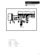
Page 23: ...ow o Orange Spark Electrode Ignition PCB Control PCB Condensate Trap Detection Electrode Gas Valve Mains Input Optional Pump Feed Transformer Overheat Stat Casing Stat Thermistor Dry Fire Flow Switch DC Fan User PCB br br w g y g y br b b b b bk br bk bk bk bk bk r r r br g w N P F bk S L Pump L N br b o o o o o o o o g y br r b bk Earth Electrode ...

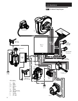
Page 24: ... Trap Sensing Electrode bk bk w w br r b br b br br br bk bk bk b w b y r v g o bk bk b bk r r b bk g y g y g y Flow Switch Fan Control PCB Interface PCB Mains Input Transformer Safety Thermostat Fan Protection Thermostat Flow Temperature Thermistor Gas Valve Spark and Earth Electrode Earth Earth r r br w w g g br b Connector with blue label g y g y b b b br br Pump ...

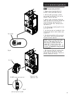
Page 25: ...to the ON position and check for gas soundness up to the gas valve 6 Turn the boiler control knob fully clockwise to HIGH Fig 34 and run the system and check the boiler for correct operation NOTE The boiler is self regulating and the gas rate will modulate between inputs of 33 76kW and 10 2kW dependent upon the system load The input is factory set at 24 5kW and can be altered to 33 76kW see sectio...

Page 26: ...ser in the operation of the boiler controls Hand over the Users Operating Installation and Servicing Instructions and the Log Book giving advice on the necessity of regular servicing 7 Advise the user that they may observe a plume of vapour from the flue terminal and that it is part of the normal operation of the boiler IMPORTANT This boiler is fitted with an aluminium alloy heat exchanger It is i...

Page 27: ...boiler are isolated 5 Remove the outercase and lower door panel see Fitting the Outercase Section 11 0 6 Release the four 1 4 turn screws securing the air box door panel and remove the door Fig 39 7 Disconnect the three lead terminals from the combustion box door taking note of their positions Fig 39 8 Undo the four screws securing the combustion box door and remove the door Fig 40 9 Visually chec...

Page 28: ...are Clean and if necessary replace the burner Fig 43 see note page 26 h Loosen the two screws retaining the heat exchanger support bracket and slide to the left to remove Fig 43 i Remove the four screws securing the heat exchanger combustion box base and withdraw the base j Lower the central insulation panel and check condition Fig 43 Replace the lower insulation pad if necessary k Ensure the heat...

Page 29: ...he system as necessary There are 3 drain points a Flow Valve b Heat Exchanger Manifold c Return Valve NOTE Do not use the Pressure Relief Valve to drain the circuit NOTE When reassembling always fit new O rings ensuring their correct location on the spigot Green O rings are used for gas joints and Black O rings for water joints Use Greasil 4000 Approved Silicone Grease 3 After changing a component...

Page 30: ...e pipe 4 Fit the new thermistor or safety thermostat and reassemble in reverse order 13 5 Expansion Vessel Fig 48 1 Drain the boiler see Section 13 1 paragraph 2 3 2 Loosen the securing screw at the base of the expansion vessel 3 Whilst supporting the vessel undo the expansion vessel connection and retain the sealing washer 4 Remove the expansion vessel 5 Fit the new expansion vessel and reassembl...

Page 31: ...the new pump and reassemble in reverse order 13 9 Pump Head Only Fig 52 1 Drain the boiler see Section 13 1 paragraph 2 3 2 Unplug the wiring harness from the pump 3 Remove the four socket head screws securing the pump head and separate it from the housing 4 Remove the screws retaining the pump electrical covers on the original and replacement heads 5 From the replacement UPS 15 60 pump head remov...

Page 32: ...hrough facia Fig 57 4 Fit new pressure gauge and reassemble in reverse order 13 12 Pressure Relief Valve Fig 58 1 The pressure relief valve is positioned on the hydraulic manifold at the back of the pump 2 Drain the boiler see Section 13 1 paragraph 2 3 3 Disconnect the union between the valve and the discharge pipe 4 Slacken the screw retaining the valve 5 Pull the valve upwards to disengage it 6...

Page 33: ...e new control board and reassemble in reverse order 13 14 Ignition Board Fig 61 1 Remove the control board 13 5 and slide out the ignition board left hand side and disconnect the electrical connections noting their positions 2 Fit the new ignition board and reassemble in reverse order 13 15 Transformer Fig 62 1 Remove the transformer connection from the control board 2 The transformer is mounted t...

Page 34: ...trode lead to prevent tracking 13 17 Fan Fig 65 1 Loosen the screw holding the injector pipe into the venturi 2 Remove the electrical connections to the fan protection sensor on the fan 3 Remove the wing nuts securing the fan to the base of the combustion box 4 Lower the fan and remove 5 Disconnect the electrical supply from the right hand rear of the fan 6 If changing the fan remove the screws se...

Page 35: ... the air box holding the gas valve 6 Remove the gas valve from the airbox side 7 Remove the nut union aluminium spacer and its gasket from the gas valve 8 Fit the nut union aluminium spacer and its gasket to the new valve 9 Fit the new gas valve and reassemble in reverse order 13 20 Condensate Trap Fig 67 1 Disconnect the condensate trap from the base of the heat exchanger 2 Disconnect the condens...

Page 36: ... Drain the boiler see section 13 1 paragraph 2 3 2 Remove all components in the base of the airbox 3 Remove the screws securing the flow switch and return connections and remove the connections Fig 70 4 Remove the electrical connections from the P C B s 5 Remove the screws securing the heat exchanger manifold and remove the manifold Fig 71 6 Lift the heat exchanger assembly Fig 72 and rotate the b...

Page 37: ...ove the lower insulation pad 6 Fit the new insulation pad and reassemble in reverse order 13 24 Heat Exchanger Upper Insulation Pad Fig 73 1 Remove all components in the base of the airbox 2 Remove the burner see section 13 21 3 Remove the heat exchanger see section 13 22 4 Remove the four bolts securing the combustion box base 5 Remove the combustion box base 6 Pull the central insulation panel d...

Page 38: ...Lockout LED flashing once every 4 seconds Go to THERMISTOR OPEN CIRCUIT section of the fault finding instructions YES NO NO YES NO YES NO YES HIGH LOW Overheat or Lockout Red Boiler On Yellow Mains On Green Control Knob Please Check Following Points Before Going Through The Fault Finding Chart Check electrical system earth continuity short circuit resistance to earth fuse failure and a minimum vol...

Page 39: ...ntrol PCB Replace transformer Check for short circuits on control PCB and fan If OK replace fuse Rectify wiring Replace control PCB Replace interface PCB YES NO Is there 24 V ac at control PCB transformer 24V connection D NO NO NO NO NO NO NO YES YES YES YES YES YES YES Mains LED Off Spark Electrode Ignition PCB Control PCB Condensate Trap Detection Electrode Gas Valve Mains Input Optional Pump Fe...

Page 40: ...B NO NO NO YES YES YES Mains LED Flashing Spark Electrode Ignition PCB Control PCB Condensate Trap Detection Electrode Gas Valve Mains Input Optional Pump Feed Transformer Overheat Stat Casing Stat Thermistor Dry Fire Flow Switch DC Fan User PCB br br w g y g y br b b b b bk br bk bk bk bk bk r r r br g w N P F bk S L Pump L N br b o o o o o o o o g y br r b bk Earth Electrode F ...

Page 41: ...YES YES YES Spark Electrode Ignition PCB Control PCB Condensate Trap Detection Electrode Gas Valve Mains Input Optional Pump Feed Transformer Overheat Stat Casing Stat Thermistor Dry Fire Flow Switch DC Fan User PCB br br w g y g y br b b b b bk br bk bk bk bk bk r r r br g w N P F bk S L Pump L N br b o o o o o o o o g y br r b bk Earth Electrode G Is pump running YES NO R Is wiring to pump OK R ...

Page 42: ...0 C Safety thermostat open circuit measured at safety thermostat NO YES YES NO NO NO YES YES NO Safety Lockout Open circuit across thermistor connections Open circuit across thermistor connections on control PCB Replace thermistor YES NO NO Thermistor Open Circuit Is flowtemperature thermistorresistancebetween 0 5k and20k measured atflowtemperature thermistor Spark Electrode Ignition PCB Control P...

Page 43: ...hort circuit when on and open circuit when off J Replace control PCB YES YES YES NO NO NO NO No Lockout Reset No Fan YES YES NO NO Is flow temperature thermistor between 0 5k and 20k measured at flow temperature thermistor Replace flow temperature thermistor red Is control PCB sensor connections 0 5k to 20k I Wiring from control PCB to sensor faulty Replace control PCB Spark Electrode Ignition PCB...

Page 44: ... gas check at meter Is there 230V at control PCB connection to ignition PCB M Is there gas but no spark Is spark probe damaged Replace spark probe Is there spark but no gas Is there 230V at ignition PCB connection to gas valve O Replace ignition PCB Replace control PCB Is the detection probe damaged Is wiring from ignition PCB to detection probe OK Rectify wiring Replace detection probe Ignition L...

Page 45: ...ere 230Vdc at the end of the gas valve lead Replace gas valve lead Replace gas valve Replace control PCB Is there 230V ignition PCB burner on pin to control PCB P Replace ignition PCB Burner On wiring from ignition PCB to control PCB faulty Is there 230V control PCB burner on pin to ignition PCB Q NO YES YES NO NO YES YES NO NO NO NO YES YES YES YES NO NO Spark Electrode Ignition PCB Control PCB C...

Page 46: ...242235 64 E06 064 Control PCB 63 E06 065 Ignition PCB 241838 65 E06 066 Transformer 240236 19 E06 074 Fan 242472 32 E06 075 Gas Valve 242473 67 E06 079 Interface PCB 241839 12 E06 085 Viewing Window 242484 22 E06 086 Condensate Trap 242485 14 E06 091 Electrodes Kit 242490 29 E06 093 Burner Assy 242492 8 E06 097 Heat Exchanger Assy 242497 46 E02 762 Pump 241157 40 36 41 64 63 65 19 32 67 12 22 29 8...

Page 47: ...he domestic heating market Gas Central Heating Boilers Wall Floor and Fireside models Independent Gas Fires Renewal Firefronts Gas Wall Heaters Solid Fuel Fires If you require information on any of these products please write telephone or fax to the Sales Department ...

Page 48: ...Potterton Baxi UK Limited Brownedge Road Bamber Bridge Preston Lancashire PR5 6SN After Sales Service 08706 096 096 Technical Enquiries 08706 049 049 www baxi com Comp No 5106703 Iss E 2 02 ...

Reviews: