


13.0
Changing Components
32
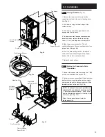
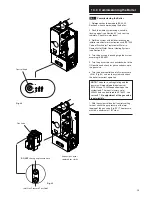
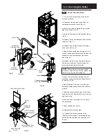
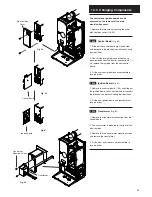
13.10
Interface PCB
1. Pull the control knob off the spindle and
remove the securing nut and washer (Fig. 53).
2. Lift the PCB from the facia box and remove
the electrical connections (Fig. 54).
3. Fit the new PCB and reassemble in reverse
order.
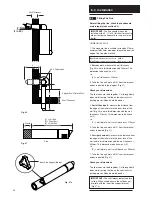
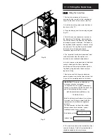
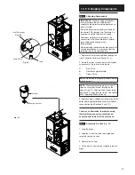
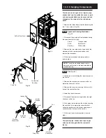
13.11
Pressure Gauge
1. Drain the boiler
(see Section 13.1 paragraph 2 & 3).
2. Undo the nut retaining the capillary in the
connection at the return pipe (Fig. 56).
3. Depress the two lugs on either side of the
pressure gauge and feed through facia (Fig. 57).
4. Fit new pressure gauge and reassemble in
reverse order.
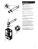
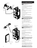
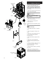
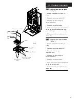
13.12
Pressure Relief Valve
(Fig. 58)
1. The pressure relief valve is positioned on the
hydraulic manifold at the back of the pump.
2. Drain the boiler
(see Section 13.1 paragraph 2 & 3).
3. Disconnect the union between the valve and
the discharge pipe.
4. Slacken the screw retaining the valve.
5. Pull the valve upwards to disengage it.
6. Fit the new pressure relief valve and
reassemble in reverse order.
Control
Knob
Securing
Nut
Washer
Fig. 53
Fig. 56
Lug
Capillary
Return Pipe
Pressure Gauge
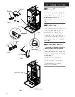
Expansion Vessel
removed for clarity
Fig. 54
Fig. 55
Fig. 57
Fig. 58
Facia Box
Interface PCB
Electrical
Connections
Pressure Relief Valve


