background image

41


PDC 2000/3000 Repair Manual

  Testing & Adjustment

4. Double click on the Collimation VI icon.  This action loads the selected LabView VI test

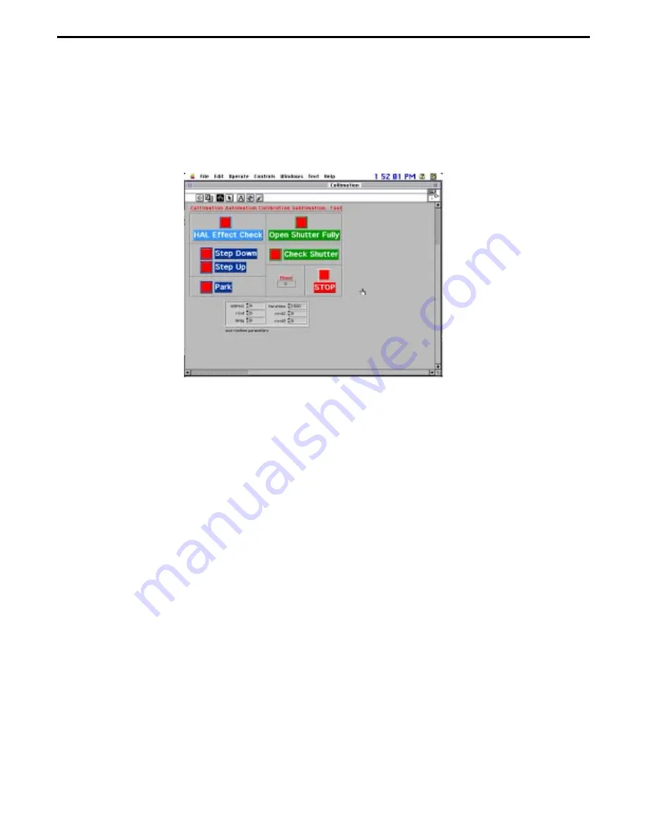
program.

5. Once the LabView VI test program is loaded, the collimation front panel appears.

6. Click on the white run arrow.  Arrow should change to black.

7. Click on the red Park button.  Camera should reset (go into its park mode).

Summary of Contents for PDC 3000

Page 1: ...Repair Manual Americas Business Center Technical Services 201 Burlington Road Bedford MA 01730 TEL 1 781 386 5309 FAX 1 781 386 5988 PDC2000 3000 Digital Cameras January 1998 ...

Page 2: ...iew 15 Overview 15 Front Panel 16 Block Diagram 16 Icon Connector 16 Test Software 16 Tester Operation 17 Starting the Tester 17 Stopping the Tester 17 Quitting the Tester 17 TestingandAdjustmentGuidelines 18 Testing and Adjustments 19 Current Profile Test 19 Required Test Equipment and Tools 19 EquipmentSetup 19 Test Procedure 21 Calibration 23 Required Test Equipment and Tools 23 EquipmentSetup ...

Page 3: ...ure 50 Dimestore 52 Required Test Equipment and Tools 52 EquipmentSetup 52 Test Procedure 53 Big Hose 57 Required Test Equipment and Tools 57 EquipmentSetup 57 Test Procedure 58 Clean Sweep 60 Required Test Equipment and Tools 60 EquipmentSetup 60 Test Procedure 61 4 Diagnostics and Troubleshooting 63 Repair Check List 63 TroubleshootingCameraMalfunctions 64 TroubleshootingGuides 69 Physical Defec...

Page 4: ...val 98 LCD Assembly Installation 98 Autofocus Board Removal 99 Autofocus Board Installation 99 Input Output Board Assembly Removal 100 Input Output Board Assembly Installation 101 List of Illustrations Figure Page 1 1 Polaroid digital camera model PDC 2000 5 2 1 Picture data flow through PDC 2000 9 2 2 Median filter interpolator function 11 2 3 High resolution mode processing within host 13 3 1 Cu...

Page 5: ...and hard drive IDE board 90 5 9 Removing power supply strobe board 91 5 10 Protective tape and foam block location 92 5 11 Installing power and SCSI overmold 93 5 12 Location of strap lugs 94 5 13 Removing edit board 96 5 14 Removing shutter board 97 5 15 Removing LCD board 98 5 16 Removing autofocus board 99 5 17 Removing input output board assembly 100 5 18 Protective tape over input output boar...

Page 6: ... PicturePro or Adobe Photoshop and the Polaroid PDC 2000 plug in software on a Macintosh computer or PC users can view the pictures taken with the PDC 2000 camera and transfer them to their computer via a standard SCSI 2 interface They can then use image processing software to manipulate enhance save and print the pictures When the camera is connected to a computer the camera can be controlled and...

Page 7: ... to produce the high resolution images resolution is not selected until pictures are being transferred to the computer Power for the camera is provided by four AA rechargeable NiCad batteries These batteries can be charged in the camera using the battery charger provided with the camera The camera is operable while the batteries are charging An LCD panel on the camera provides information about ti...

Page 8: ...on colors 5 6MB file Image storage PDC 2000 40 40 images capacity PDC 2000 60 60 images PDC 2000 T No internal storage for images Computer interface SCSI 2 Standard lens f 2 8 11mm 38mm equivalent Focus range 10 inches to infinity Equivalent film speed ISO 100 Shutter Scanning aperture shutter microprocessor controlled Shutter speed 1 25 to 1 500 seconds Aperture f 2 8 f 11 Flash Internal up 15 fe...

Page 9: ...ortable PCs using the PCMCIA slot 4 pack rechargeable AA NiCad batteries Eveready 5 hour charger 12 volt auto adapter Polaroid camera bag Macintosh operating Apple Macintosh or Powerbook computer with a 68030 or requirements later processor Macintosh system software version 7 1 or later 8 megabytes of available RAM 16 MB recommended 10 megabytes of available hard disk space IBM compatible IBM PC o...

Page 10: ...igital data is processed through the following modules CCD sensor Video signal processor Frame buffer Internal storage Median filter interpolator SCSI interface Figure 2 1 Picture data flow through PDC 2000 Back End Digital Board Light from Scene Optics Module Front End Analog Board CCD Video Signal Processor Frame Buffer Internal Storage Median Filter Interpolator SCSI Interface Picture Data to H...

Page 11: ...Mode The median filter interpolator converts RGB triplets received from the frame buffer to an 800 x 600 standard resolution for the PDC 2000 RGB image by arranging the pixels and averaging adjacent horizontal pixels as shown in Figure 2 2 It sends the reconstructed pixel data to the SCSI interface ...

Page 12: ...PDC 2000 3000 Repair Manual Theory of Operation 12 Figure 2 2 Median filter interpolator function Median Filter Interpolator From Frame Buffer To SCSI Interface and Host Computer ...

Page 13: ...n the high resolution mode 1600 x 1200 instead of standard resolution data from the frame buffer passes directly to the SCSI interface without passing through the camera s median filter interpolator Figure 2 1 In this high resolution mode the host computer processes the frame buffer data to produce a 1600 x 1200 pixel image as shown in Figure 2 3 ...

Page 14: ...r Manual Theory of Operation 14 Figure 2 3 High resolution mode processing within host From Camera Frame Buffer Via SCSI Interface High Resolution Proccessing Host Computer To Image Processing Application on Host Computer ...

Page 15: ...ign a test program Refer to the LabView User s Guide for more detailed information pertaining to the LabView components necessary to design a test program Front Panel The front panel is the user interface It serves as an interactive interface for supplying inputs to and observing outputs from the instrumentation system LabView makes creating a front panel as simple as drawing a picture and gives t...

Page 16: ...ware National Instrument and Concept VI Image Processing Library Graftek It is intended to help the repair person diagnose PDC 2000 3000 digital camera malfunctions Programs developed using LabView are called virtual instruments VI s The developed software consists of a Tester which invokes the necessary sub VI s routines that allow the repair person to check the PDC 2000 3000 digital camera When ...

Page 17: ...the test panel Also a test report and the Pass Fail indicators displayed on the test panel are updated Stopping the Tester Note The Tester should not be stopped in the middle of a test sequence However if an emergency situation occurs use the following steps to stop and restart the Tester 1 Click the mouse on the stop box to completely stop the camera s test sequence The black arrow changes to a w...

Page 18: ...many windows and dialog boxes appear and disappear throughout the test process Use the following test guidelines to perform the requested user tasks Yes No Click on appropriate response Yes or No DialogBoxes Message Windows Perform requested task and then click on Start button w Start Button AutoSequence No user input Windows ...

Page 19: ...ure 3 1 1 Place the camera onto a workbench 2 Connect the external power supply output cable to the 6 Vdc input on the 1 ohm resistor box 3 Connect the 1 ohm resistor box 6 Vdc output cable to the camera power jack 4 Connect the computer ribbon cable to the 1 ohm resistor box 5 Turn on the test equipment as follows Macintosh Centris 650 computer On Off 0 1 switch to On 1 0 10 Vdc external power su...

Page 20: ...ment setup Macintosh Centris 650 Power PC External Power Supply 6 Vdc PDC2000 3000 Camera Test Fixture Nest 1 Ohm Resistor Box Ribbon Cable not shown Out to computer 6 Vdc Out to PC Grn Manual LV LabView Switch 6Vdc In From external power supply 1 Ohm Resistor Box Grn Equipment Setup ...

Page 21: ...HD windows appears 3 Double click on the Current Profile VI icon This action loads the specified LabView VI test program 4 Once the LabView VI test program is loaded the Cam Power New VI panel appears 5 Set the 1 ohm resistor box Manual LV switch to Manual 6 Turn on the digital camera under test Note Make sure camera strobe is turned off HD Icon ...

Page 22: ... the test program runs Click on the appropriate responses that appear in the dialog boxes 10 Upon completion of the current profile test program current waveforms for the following appear Current Amperes Waveform should be smooth Reference Current Amperes Waveform should be smooth Difference Current Amperes Not used Filtered Windowed Difference current Amperes Not used Note Spikes displayed in the...

Page 23: ...nt PDC2000 Switching Power Supply Camera SCSI Cable Camera Test Fixture Nest Keithly 485 AutoRanging Picoammeter or Equivalent Polaroid Model B Light Source PDC Blue Box with Photodiode attached to glass Graywall Booth Diorama Test Bench PDC Diorama Camera Test Fixture Nest MacBeth Color Chart Neutral Density Filter AuxiliaryStrobe ...

Page 24: ... to the camera s external power connector 4 If applicable set the camera s SCSI ID to 4 5 If applicable replace camera lens with an 11mm lens Note 11mm lens is standard Some camera s come in for repair with the optional 17mm lens attached For testing purposes the standard 11mm lens must be used 6 Turn on the test equipment as follows Power Computing PC On Off 0 1 switch to On 1 Keithly 485 AutoRan...

Page 25: ...nt setup Figure 3 3 Strobe setup Camera Power Supply Power Computing Power PC Camera SCSI Cable Model B Light Box Camera Nest Picoammeter PDC 2000 3000 Camera Camera SCSI Cable PDC 2000 3000 Camera Power Computing Power PC Graywall Booth Camera Power Supply Photodiode ...

Page 26: ... Camera Power Supply Power Computing Power PC PDC 2000 3000 Camera Camera SCSI Cable Diorama Camera Nest Diorama Bench Auxiliary Strobe Neutral Density Filter Checker Resolution Target Camera SCSI Cable Power Computing Power PC Camera Power Supply Diorama Bench PDC 2000 3000 Camera Auxiliary Strobe Neutral Density Filter Diorama Camera Nest Macbeth Color Checker Chart Resolution Chart ...

Page 27: ... Manual Testing Adjustment Figure 3 6 Color and focus test vertical Camera SCSI Cable Power Computing Power PC Camera Power Supply Diorama Bench PDC 2000 3000 Camera Auxiliary Strobe Neutral Density Filter Diorama Camera Nest ...

Page 28: ...older The PDC Calibration window appears 4 Double click on the applicable Calibration icon The Calibration window appears Notes 40 60 hard drive camera type click on V3 020 icon Tither camera type click on V3 021 icon 5 Double click on the Calibration iib icon This action loads the specified LabView VI test program 6 Once the LabView VI test program is loaded the Calibration front panel appears HD...

Page 29: ...s Note If the camera is not turned on turn on the camera under test and then repeat step 7 through 9 10 Click on the Start button to automatically start the ambient part of this calibration procedure Note Follow all instructions that appear on the screen while the ambient part of this calibration procedure runs Click on the appropriate responses that appear in the dialog boxes 11 Upon completion o...

Page 30: ... start the strobe part of this calibration procedure Note Follow all instructions that appear on the screen while the strobe part of this calibration procedure runs Click on the appropriate responses that appear in the dialog boxes 14 Upon completion of the strobe part of the calibration procedure a prompt appears indicating that the camera be moved to the Diorama bench Figure 3 4 ...

Page 31: ...in the dialog boxes 18 Upon completion of the first part of the focus calibration procedure a prompt appears indicating that the camera be setup for the horizontal part of the focus calibration procedure Figure 3 5 19 Flip up the checker resolution target Figure 3 5 20 Slide the horizontal target over the checker resolution target Camera should be aimed at horizontal target Figure 3 5 21 Click on ...

Page 32: ...cker resolution target Camera should be aimed at vertical target Figure 3 6 25 Click on the Start button to automatically start the vertical part of the focus calibration procedure Note Follow all instructions that appear on the screen while the vertical part of the focus calibration procedure runs Click on the appropriate responses that appear in the dialog boxes 26 Upon completion of the vertica...

Page 33: ...33 PDC 2000 3000 Repair Manual Testing Adjustment ...

Page 34: ...r to the camera SCSI connector 3 Connect the switching power supply cable to the camera s external power connector 4 If applicable set the camera s SCSI ID to 4 5 If applicable replace camera lens with an 11mm lens Note 11mm lens is standard Some camera s come in for repair with the optional 17mm lens attached For testing purposes the standard 11mm lens must be used 6 Turn on the test equipment as...

Page 35: ...erformance test setup Test Procedure 1 If applicable enter user password 2 Double click on the hard drive HD icon The HD windows appears Kyoritso Light Box PDC 2000 3000 Camera Camera SCSI Cable Power Computing Power PC Camera Power Supply Universal Camera Nest HD Icon ...

Page 36: ...l appears Notes PDC 2000 3000 40 60 hard drive camera type click on V 020 icon Tither camera type Use IP VI for DMC 5 Click on the white arrow Arrow should change to black 6 Click on the green Start button to automatically start the selected LabView VI test program Note Follow all instructions that appear on the screen while the image performance procedure runs Click on the appropriate responses t...

Page 37: ...ce procedure the screen displays a panel indicating whether or not a particular image performance test passed Pass or failed Fail Note The following test must Pass for the camera to be OK Config Kitty Test CR Contrast CS Color Shift All other tests can indicate Fail and camera would still OK ...

Page 38: ...the host computer SCSI connector to the camera SCSI connector 2 Connect the switching power supply cable to the camera s external power connector 3 If applicable set the camera s SCSI ID to 4 4 If applicable replace camera lens with an 11mm lens Note 11mm lens is standard Some camera s come in for repair with the optional 17mm lens attached For testing purposes the standard 11mm lens must be used ...

Page 39: ...ocedure 1 If applicable enter user password 2 Double click on the hard drive HD icon The HD windows appears 3 Double click on the collimation folder The Collimation window appears HD Icon Camera SCSI Cable Mac Centris 650 Computer Camera Power Supply PDC 2000 3000 Camera Diorama Camera Nest ...

Page 40: ...tion VI icon This action loads the selected LabView VI test program 5 Once the LabView VI test program is loaded the collimation front panel appears 6 Click on the white run arrow Arrow should change to black 7 Click on the red Park button Camera should reset go into its park mode ...

Page 41: ...ng Power Supply Camera SCSI Cable Camera Test Fixture Nest Equipment Setup Figure 3 9 1 Place the camera onto the test fixture camera nest 2 Connect the camera SCSI cable from the host computer SCSI connector to the camera SCSI connector 3 Connect the switching power supply cable to the camera s external power connector 4 If applicable set the camera s SCSI ID to 4 5 If applicable replace camera l...

Page 42: ... enter user password 2 Double click on the hard drive HD icon The HD windows appears 3 Double click on the applicable camera PDC 2000 or PDC 3000 Serial Number VI This action loads the selected LabView VI test program HD Icon Camera SCSI Cable Mac Centris 650 Computer Camera Power Supply PDC 2000 3000 Camera Diorama Camera Nest ...

Page 43: ...cable camera type 6 Click on the Configuration Box and then enter the camera configuation code 6 Click on Customize Serial Number window 7 Click on the white run arrow Arrow should change to black The Password Checker VI window appears Note If Lock symbol is displayed enter password exactly as shown No space Initial Cap rest lower case Unlock Configuration Code Camera Serial Number 079617 34 GQ K4...

Page 44: ...e K40 F20 F40 F60 TOO PO3 Example 079624 15GQ F60 Note Need decimal to hex conversion chart to properly enter camera serial number 9 Click on Chip symbol button A message window appears indicating the serial number that was entered is about to be written into memory 10 Check the serial number to be entered Notes If the serial number to be entered is correct click on OK If the serial number to be e...

Page 45: ...r resolution target 3 Connect the camera SCSI cable from the host computer SCSI connector to the camera SCSI connector 4 Connect the switching power supply cable to the camera s external power connector 5 If applicable set the camera s SCSI ID to 4 6 If applicable replace camera lens with an 11mm lens Note 11mm lens is standard Some camera s come in for repair with the optional 17mm lens attached ...

Page 46: ...ser password 2 Double click on the hard drive HD icon The HD windows appears 3 Double click on the Fast Flatness VI This action loads the selected LabView VI test program HD Icon Camera Power Supply Mac Centris 650 Computer PDC 2000 3000 Camera Camera SCSI Cable Diorama Camera Nest Diorama Bench Checker Resolution Target ...

Page 47: ...nge to black This action starts the selected LabView VI test program 8 Upon completion of the Fast Flastness Test procedure the Fast Flatness Test front panel indicates the Peak Tolerances Location Notes If the Top Bottom and Left Center Right buttons are green camera focus OK Peak Tolerances Location high point should be at 42 4 If the Top Bottom and Left Center Right buttons are red camera focus...

Page 48: ... 2 Connect the camera SCSI cable from the host computer SCSI connector to the camera SCSI connector 3 Connect the switching power supply cable to the camera s external power connector 4 If applicable set the camera s SCSI ID to 4 5 If applicable replace camera lens with an 11mm lens Note 11mm lens is standard Some camera s come in for repair with the optional 17mm lens attached For testing purpose...

Page 49: ...f applicable enter user password 2 Double click on the hard drive HD icon The HD windows appears 3 Double click on the Peak Tweak VI This action loads the selected LabView VI test program HD Icon Camera SCSI Cable Mac Centris 650 Computer Camera Power Supply PDC 2000 3000 Camera Diorama Camera Nest ...

Page 50: ...anel appears 5 Click on the white run arrow Arrow should change to black 6 Once the camera is fined tuned the Bingo Close Enough or Reject windows indicate the pass or fail status Notes If the Bingo or Close Enough window lights up camera focus OK If the Reject windows lights up camera focus incorrect Re collimate camera ...

Page 51: ...Nose Pliars Equipment Setup Figure 3 12 1 Place the camera onto the PDC Diorama Camera Test Fixture Nest 2 Flip up the checker resolution target Camera should be aimed at checker resolution target 3 Open the camera 4 Using tweezers or needle nose pliars gently remove the red pin from the focus gear 5 Manually move the focus gear to its home start position 6 Connect the camera SCSI cable from the h...

Page 52: ...17mm lens attached For testing purposes the standard 11mm lens must be used 10 Turn on the test equipment as follows Mac Centris 650 Computer On Off 0 1 switch to On 1 Turn on the camera Figure 3 12 Dimestore setup Camera Power Supply Mac Centris 650 Computer PDC 2000 3000 Camera Camera SCSI Cable Diorama Camera Nest Diorama Bench Checker Resolution Target Focus Gear Focus Gear Pin ...

Page 53: ... 2 Double click on the hard drive HD icon The HD windows appears 3 Double click on the DimeStore VI This action loads the selected LabView VI test program 4 Once the LabView VI test program is loaded the DimeStore front panel appears 5 Click on the white run arrow Arrow should change to black HD Icon ...

Page 54: ...Using tweezers or needle nose pliars gently reinsert the red pin into the focus gear 9 Once the red pin is inserted into the focus gear click on OK 10 Click on the Toward button to rotate the focus gear to its Home start position 11 Click on the Away button to rotate the focus gear 2 or three steps from its home position 12 Click on the Write it button to write the new focus information into the c...

Page 55: ... test Note Make sure that the peak values are changed to the current peak values before runningtest 16 Re park the camera again 17 Runthe Peak Tweak test 18 Re park the camera again 19 Re run the Fast Flatness test Notes If the Peak Tolerances Location high point is at 42 4 camera focus OK If the Peak Tolerances Location high point is not at 42 4 camera out of focus repeat Dime Store test procedur...

Page 56: ...e camera onto the test fixture camera nest 2 Connect the camera SCSI cable from the host computer SCSI connector to the camera SCSI connector 3 Connect the switching power supply cable to the camera s external power connector 4 If applicable set the camera s SCSI ID to 4 5 If applicable replace camera lens with an 11mm lens Note 11mm lens is standard Some camera s come in for repair with the optio...

Page 57: ... If applicable enter user password 2 Double click on the hard drive HD icon The HD windows appears 3 Double click on Big Hose VI This action loads the selected LabView VI test program HD Icon Camera SCSI Cable Mac Centris 650 Computer Camera Power Supply PDC 2000 3000 Camera Diorama Camera Nest ...

Page 58: ...on the run arrow It instantly indicates that the camera is connected upon clicking on the run arrow 6 Unplug the camera power connector and then reconnect it The camera window will indicate that the internal hard drive is now set for 60MB Note Never power down the camera with the camera On Off button 7 Run the Serial Number VI test to rewrite the camera s internal serial number to match the serial...

Page 59: ...xture Nest 2 Flip up the checker resolution target Camera should be aimed at checker resolution target 3 Connect the camera SCSI cable from the host computer SCSI connector to the camera SCSI connector 4 Connect the switching power supply cable to the camera s external power connector 5 If applicable set the camera s SCSI ID to 4 6 If applicable replace camera lens with an 11mm lens Note 11mm lens...

Page 60: ...ser password 2 Double click on the hard drive HD icon The HD windows appears 3 Double click on the Clean Sweep VI This action loads the selected LabView VI test program HD Icon Camera Power Supply Mac Centris 650 Computer PDC 2000 3000 Camera Camera SCSI Cable Diorama Camera Nest Diorama Bench Checker Resolution Target ...

Page 61: ...splay Image button the image of the checker resolution target will appear each time the camera cycles takes a picture To continue the process you must click on OK 6 Click on the white run arrow Arrow should change to black The Erasing clock starts to count down as each picture of the checker resolution target is taken 7 Once the Erasing clock counts down to zero all pictures stored in camera memor...

Page 62: ...oftware to take pictures if the camera is a PDC 2000 T 1 Power up the camera with Batteries and then External Power Adapter Trickle Charger 2 Check all User buttons and interface functions 3 Check camera viewfinder for visual defects dirty internal debris aiming lens edges skewed or damaged 4 Look at the Customers pictures on the camera hard drive card to determine cause of its malfunction 5 Take ...

Page 63: ...the lens assembly Remove the eyecup retainer and the eyecup from the viewfinder assembly Open the rubber SCSI connector door and remove the two 2 screws from inside the compartment Turn the camera over and remove the four 4 remaining screws that secures the top cover to the bottom cover assembly Note Location of four 4 remaining screws Two 2 from the battery tray area Two 2 from either side of the...

Page 64: ...bottom cover Figure 4 2A Black masking tape placed between rear lens and shutter to prevent light from leaking into camera Figure 4 2B Black masking tape placed on the side of the strobe lamp to prevent seeing the shiny side of strobe when the camera is closed Figure 4 2C Foam pad placed between bottom cover screw post and flex to prevent flex from shorting to bottom cover Figure 4 2D Foam Pad Top...

Page 65: ...d on strobe capacitor Figure 4 2G All flex cables for tears breaks poor connection not seated properly or locked etc Notes If necessary use a jewels magnification loop to visually inspect any or all of the flex cables Camera connectors have locking tabs which secures its flex cable in place To remove a flex cable first pull back the two locking tabs and pull it free of the connector When installin...

Page 66: ...ween body of strobe and bottom cover Tape placed on bottom cover Tape placed between rear lens and shutter PDC2000 only Foam pad on strobe capacitor Tape securing optical flex Foam pad between flex and screw post A B C D F E Tape over IO Board G Molded plastic instead of tape between rear lens and shutter PDC3000 only ...

Page 67: ... replacement component can be temporarily connected to the camera to determined if that particular component is at fault Note If this approach to troubleshooting is used always make sure that the component is insulated Figure 4 3 from all other components so that it will not short out or damage other components of the camera when the camera is turned on If it is determined that the temporarily con...

Page 68: ...to stick reposition applicable PC board Button location Edit PC board Erase Label Enter Scroll Autofocus PC board AF Flash Shutter PC board WB White Balance Index Shutter Black Backlight Compensation Power PC board Power On Off Inoperative Defective button s Replace applicable PC board See above for button location Damaged or disconnected Connect or replace applicable flex flex Missing Damaged N A...

Page 69: ...PC board to LCD LCD assembly assembly Defective LCD assembly Replace LCD assembly Viewfinder VF Viewfinder Lens Skewed or damaged edges Replace Top Cover with Viewfinder assembly Dirty debris External Clean Viewfinder Lens Internal Replace Top Cover with Viewfinder assembly Red Yellow LED s Damaged or disconnected Connect or replace fiber optic Not working fiber optic connection to to Autofocus PC...

Page 70: ...Troubleshooting 71 Guide 4 1 Physical Defects Cont d Problem Cause Corrective Action SCSI Door Damaged Torn or pins broken Replace SCSI door Not Fastened to Retainer broken or missing Replace retainer Bottom Cover If applicable replace SCSI door ...

Page 71: ...amaged or disconnected Connect or replace IO PC IO PC board to Back board to Back End PC End PC board flex board flex Defective IO PC board Replace IO PC board No Power Up Battery compartment not Check battery compartment Batteries Only latched properly If necessary relatch battery compartment and power up again Batteries loaded incorrectly Open battery compartment to make sure batteries are loade...

Page 72: ...splay Error Messages STUCK_BTN Button not operating Reposition Power Button smoothly Board Assembly Defective Power Button Replace Power Button Board assembly Board assembly Defective Back End Replace Back End PC board PC board 04 H System clock not Turn camera on and off to functioning correctly reset system clock If error message does not clear replace Power Supply Strobe PC board 01 H Big Hose ...

Page 73: ...tics Module assembly Will Not Power Off Defective Back End Replace Back End PC board PC board Defective Power Supply Replace Power Supply Strobe Strobe PC board PC board Will not Auto Set incorrectly Verify shut off time with host Shut Off computer software If necessary reset shut off time Big hose Run VI 1 or 2 times Defective Power Supply Replace Power Supply Strobe Strobe PC board PC board Inte...

Page 74: ...d Problem Cause Corrective Action Intermittent ON OFF Damaged or disconnected Connect or replace flex Back or flex Back End PC board to End PC board to Power Incomplete Power Up Power Strobe PC board Strobe PC board Cont d Defective Power Strobe Replace Power Strobe PC board PC board Defective Back End Replace Back End PC board PC board ...

Page 75: ...r SCSI connection Check SCSI connection If necessary wiggle SCSI connector to see if communication is established Loose SCSI connector on Tighten screws that secures IO PC board the SCSI connector to the IO PC board Defective IO PC board Replace IO PC board Damaged or disconnected Connect or replace flex Back flex Back End PC board to End PC board to IO PC IO PC board board Defective Back End Repl...

Page 76: ...s for bushing erratic curve etc AutoFocus Button Set to Off Reset Autofocus to On Defective Autofocus Replace Autofocus PC board PC board Distance Defective Sonar Replace Sonar Transducer Measurement Transducer Incorrect Defective Front End PC Replace Front End PC board board Focus Gear Missing or incorrectly Replace or reposition lens No Movement positioned lens magnet magnet Defective focus moto...

Page 77: ...t transducers connections from shorting to bottom cover Defective Sonar Replace Sonar Transducer Transducer Defective Front End PC Replace Front End PC board board Poor Picture Quality No Picture Black Lens cap on lens Remove lens cap Damaged or disconnected Connect or replace flex flex Optics Module to Optics Module to Front End Front End PC board PC board Defective shutter Replace Optics Module ...

Page 78: ...ated Recalibrate using LabView Defective Front End PC Replace Front End PC board board Half 1 2 Picture Defective Front End Replace Front End PC board Rest of picture PC board striped or no image Poor connection between Reseat connection between Hard Drive and Back End Hard Drive and Back End PC board PC board Defective Hard Drive Replace Hard Drive Damaged or disconnected Connect flex or replace ...

Page 79: ...masking tape Picture between the rear lens and theshutter as shown in Figure 2B Blue Yellow Tint Camera settings incorrect Reset camera settings Picture all one Damaged or disconnected Connect flex or replace Color or Waterfall flex CCD to Front End Optics Module Assembly of Colors PC board Defective CCD Replace Optics Module Assembly Defective Front End PC Replace Front End PC board board ...

Page 80: ...l it finds the previously made threads in the plastic then continue installing the screw When disassembling the camera you will note that protective tape is used at several locations within the camera body Be certain that all of the tape is back in place before securing the camera chassis to the top cover assembly The connectors in the camera have locking tabs which secure the harness assemblies i...

Page 81: ...replaceable components Transducer assembly Power SCSI overmold Front end board Strap Lugs Power button board Hard Drive PDC2000 only Back end board IDE board PDC3000 only Power Strobe board The top cover assembly contains the following replaceable components Top cover with viewfinder LCD assembly Edit Board Autofocus Board Shutter Board Input output Board Because of constricted space within the ca...

Page 82: ...onents Trans Front Power Back Hard Power Edit Bd ducer End Button End Drive Strobe Assy Bd Bd Bd Bd Transducer Assy Front End Bd Power Button Bd Back End Bd Hard Drive PDC2000 IDE Board PDC3000 Power Strobe Bd Power SCSI overmold Left Rear Strap Lug Right Rear Strap Lug Front Strap Lug Edit Bd Shutter Bd LCD Assy Autofocus Bd Input Output Bd ...

Page 83: ...tment Figure 5 2 Removing screws securing top cover 5 Turn the camera over and remove the four remaining screws which secure the top cover to the camera chassis assembly two from the battery tray area and two from either side of the lens housing 6 Holding the top and bottom halves together turn the camera right side up on the work surface Phillips Flat Head M2 2x9 5 Phillips Pan Head 4 M2 2x15 Eye...

Page 84: ...k end board cable from shutter board connector Back end board cable from input output board connector Back end board cable from input output board connector 9 The top cover assembly is now free of the camera chassis Top Cover Installation To install the top cover reverse the removal procedure Note Be certain that the edit board buttons are properly seated before installing the six securing screws ...

Page 85: ...ducer cable from the connector on the front end board 4 The transducer is now free of the assembly Transducer Installation To install the transducer reverse the removal procedure Note Be certain the transducer is seated in the same orientation as the one previously removed Also as shown in Figure 5 5 be sure to replace the tape over the transducer connection Lift Transducer Assembly up to limit of...

Page 86: ...ly 3 Disconnect the optics module cable from connector J1 on the front end board Figure 5 6 Figure 5 6 Removing front end board 4 Disconnect the optics module cable from connector J2 on the front end board Replace protective tape over electrical connections Pry up here Phillips Pan Head Screws 2 28x1 2 J3 J2 J1 Pry up here Phillips Pan Head Screws 2 28x1 2 Bottom Chassis Assembly ...

Page 87: ...e board from connectors on the back end board and on the power supply strobe board 7 Lift the front end board out of the camera chassis assembly Front End Board Installation To install the front end board reverse the removal procedure Note Use gentle pressure to mate the two female connectors on the bottom of the board to the male connectors on the power supply strobe board and the back end board ...

Page 88: ...erse the removal procedure Note Be certain the power button board is oriented in the same manner as the power button board previously removed Back End Board and Hard Drive IDE Board Removal 1 Remove the top cover 2 Remove the front end board 3 Remove the power button board 4 Disconnect the back end board cable from the connector on the power supply strobe board Figure 5 8 Back End Board Front End ...

Page 89: ...board out of the camera chassis Disconnect the IDE board from the back end board Back End Board and Hard Drive IDE board Installation To install the back end board and hard drive IDE board reverse the removal procedure Caution There may be a compatibility problem between the hard drive connector and the back end board if different configuration parts are mixed Generally PBO2 back end boards requir...

Page 90: ...d cable from the power supply strobe board connector Figure 5 9 Figure 5 9 Removing power supply strobe board 5 Guide the power supply strobe board assembly out from under the optics module and free of the camera chassis Note The two guide pins which are used to properly align the board in the chassis Front End Board Back End Board Cable Power Supply Strobe Board Hard Drive PDC2000 Only IDE Board ...

Page 91: ...e there is protective tape between the optical module and the lens mounting ring Figure 5 10A there must also be tape securing the optical flex Figure 5 10B in place Finally be certain there is a foam pad on top of the flash capacitor Figure 5 10C Figure 5 10 Protective tape and foam block location A C B Foam block on flash capacitor Tape securing optical flex Tape between optical module and lens ...

Page 92: ... a one piece type others have a retainer pressed into the overmold If you are replacing the latter type first press the retainer firmly into the rubber overmold and then follow the instructions below to complete the installation of the overmold into the camera 1 Align the four overmold rubber bosses into the openings in the chassis Figure 5 11 Figure 5 11 Installing power and SCSI overmold 2 Using...

Page 93: ...nterior of the camera chassis by an e ring To remove a strap lug the e ring must be removed The depth of disassembly to gain access to the e rings varies according to the location of the strap lug Follow the instructions below to determine what components must be removed to replace a strap lug Figure 5 12 Location of strap lugs Left Rear Strap Lug Under Viewfinder Eyecup 1 Remove the top cover 2 R...

Page 94: ... the optics module 4 Remove the power supply strobe board Edit Board Removal Note New edit boards include the rubber buttons 1 Remove the top cover 2 Gently rock the edit board side to side while lifting it free from between the wall of the top cover and the plastic tab which secures it Figure 5 13 Note Some cameras may have a plastic shim holding the edit board in place Be sure to reinstall it if...

Page 95: ...install the edit board reverse the removal procedure Note Be sure the edit board buttons are properly seated in the cutouts of the top cover and camera chassis assembly before securing the two assemblies together Shutter Board Disconnect Edit Board cable here Plastic Holding Tab Edit Board Top Cover Assembly ...

Page 96: ... that secure the shutter board to the top cover 6 Lift the shutter board with attached shutter button from the top cover Shutter Board Installation To install the shutter board reverse the shutter board removal procedure Note When replacing the shutter board make sure mounting hole where the Phillips flat head screw goes is counter sunk piece of thin foam is placed between the focus motor board an...

Page 97: ...ter board 5 Remove the two Phillips pan head screws which secure the LCD assembly to the top cover and lift the assembly free 6 Remove the LCD cover window from the top cover indent by simply lifting it out LCD Assembly Installation To install the LCD assembly reverse the removal procedure Note Be sure to install a new self adhesive rubber gasket on the bottom of the new LCD assembly Disconnect tw...

Page 98: ...fiber optics cable from the autofocus board The cable is extremely fragile and if damaged the entire top cover with viewfinder must be replaced 5 Remove the two Phillips pan head screws that secure the board to the top cover 6 Remove the autofocus board with the two attached rubber buttons from the top cover Autofocus Board Installation To install the autofocus board reverse the removal procedure ...

Page 99: ...l 1 Remove the top cover 2 Remove the two Phillips pan head screws securing the board to the top cover Figure 5 17 3 Remove the input output board assembly from the top cover Figure 5 17 Removing input output board assembly Phillips Pan Head Screws M2 2x4 5 Input Output Board Assembly ...

Page 100: ...stall the input output board assembly reverse the removal procedure Note Before assembling the top cover and chassis assemblies be certain tape is placed over the input output board as shown in Figure 5 18 Figure 5 18 Protective tape over input output board Protective tape over Input Output Board ...

Reviews: