background image


iNS/iDS 2-Wire System Manual 

350-077 

Rev. D  -  1/20/2021


Page 83 of 107 


12.3 

Status Page 


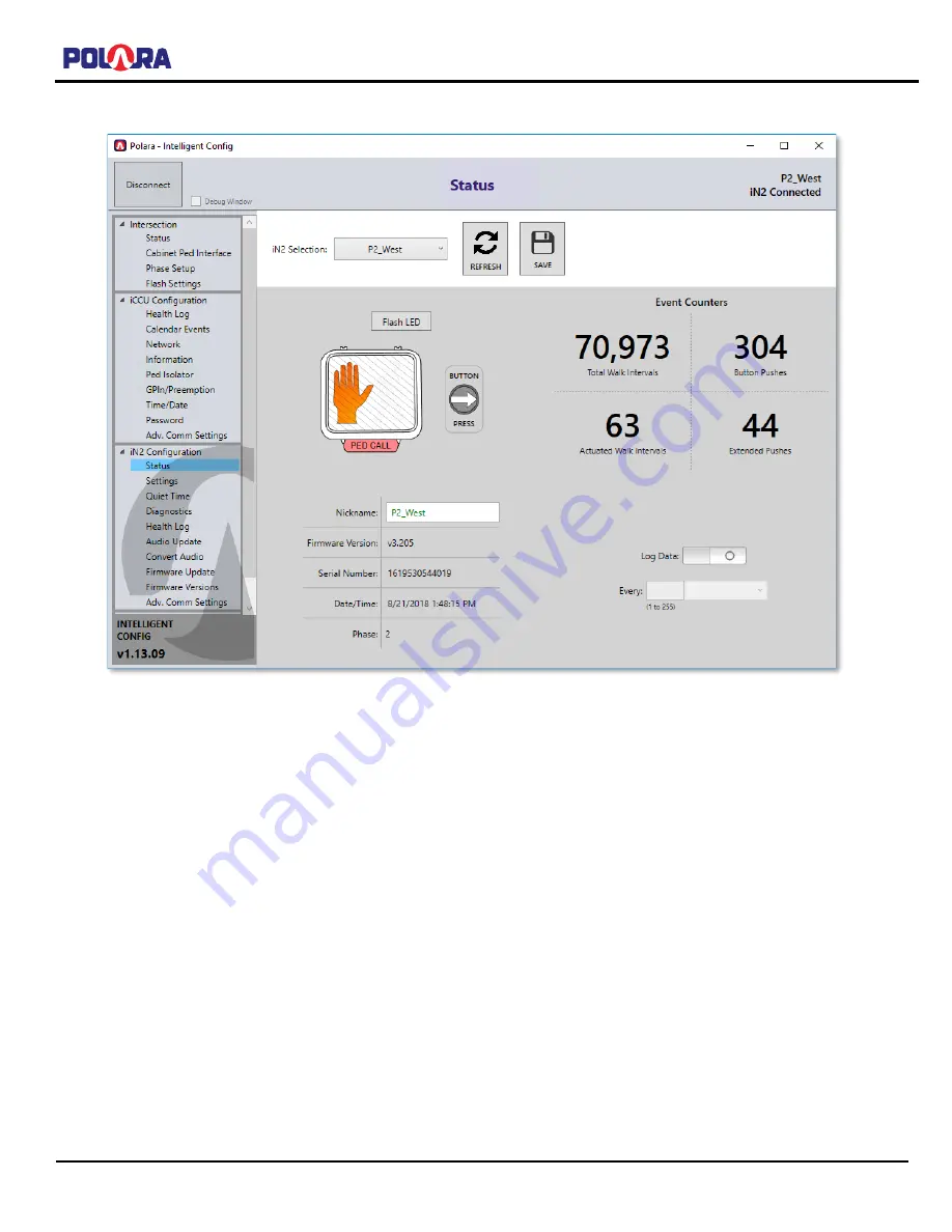
The status page provides information about the connected PBS. 

The panel on the left contains a menu of pages containing the various setup and maintenance functions. Online help is 
available on each page by hovering the mouse pointer over a function button. 

12.3.1


Assigning a Name to a PBS 

On the Status Page, enter the desired name into the Nickname field. Then click SAVE. The name of the button is 
immediately changed. Subsequent Bluetooth connections to the PBS will use the new name. 


Summary of Contents for iDS2

Page 1: ... Page 1 of 107 Polara iNS iDS 2 Wire System Manual Note Model iDS2 is equivalent to iNS2 in all aspects but includes iDetect functionality Anywhere iNS2 is used in this manual applies to iDS2 also For use with iCCU S2 and iCCU C2 350 077 Rev D 1 20 2021 ...

Page 2: ...15 3 3 1 Typical 332 or Similar Cabinet Connection 1 Preferred 15 3 3 2 Typical 332 or Similar Cabinet Connection 1 Alternate 16 3 3 3 Typical 332 or Similar Cabinet Connection 2 17 3 4 iCCU S2 Central Control Unit Installation Procedure 18 3 4 1 Cabinet Interface for Ped Intervals and Ped Calls 18 3 4 2 Preemption and General Purpose Inputs Diagram Section 3 2 4 19 3 5 iCCU C2 Central Control Uni...

Page 3: ...a Field Service App for iOS to Program Calendar Features 59 10 Using Polara Field Service App for PC to Change iCCU X2 Settings 60 10 1 Download Polara Field Service App for PC Intelligent Config Application 60 10 2 iN DGL BLE Dongle 60 10 3 Application Installation 60 10 4 Wi Fi Connection 60 10 4 1 Auto Login 61 10 4 2 Initial System Setup 62 10 5 Changing the Password 63 10 6 Advanced Communica...

Page 4: ...eration 98 16 1 Pilot LED in Traffic State 98 16 2 Pilot LED Offline Sub States and Modes 98 16 2 1 Power On Self Test Maintenance Mode 98 16 2 2 Searching for iPHCU3S or iCCU X2 Connection 98 16 2 3 No Pedestrian Interval Detected 99 16 2 4 Power On Self Test Failed 99 16 2 5 Loss of iCCU X2 Connection 99 16 3 Pilot LED Double Flash 99 17 Configuration Settings Details 100 17 1 Volume Settings 10...

Page 5: ...ime 103 17 4 3 Wait Message 103 17 4 4 Direction Message 103 17 4 5 Information Message 104 17 4 6 Push Confirm Message 104 17 5 Other Settings 104 17 5 1 Button Push Force 104 17 5 2 Cancel on Walk 104 17 5 3 Extended Push Time 104 17 5 4 Second Language 105 17 5 5 Extended Push Priority 105 17 5 6 Ping Pong 105 17 5 7 External Speaker Option 106 17 5 8 Double Walk 106 17 5 9 Limit Push Recall 10...

Page 6: ...t is used in a manner not specified by the manufacturer the protection provided by the equipment may be impaired Caution Risk of electric shock The installer must be aware of the presence of hazardous voltage levels which may be exposed during the installation of this equipment For personal safety the use of insulating gloves and safety glasses is recommended EARTH GND ground protective conductor ...

Page 7: ...o cases that apply equally to both iCCU S2 and iCCU C2 iCCU X2 shall be used 2 1 iNS2 Accessible Pedestrian Signal Push Button Station PBS The iNS2 is an Accessible Pedestrian Signal Push Button Station PBS These PBSs are typically used in pairs mounted on poles at each end of a pedestrian crosswalk Its purpose is to transmit a request for a Walk Signal to a Traffic Controller by pressing its butt...

Page 8: ...DC 5mA max Ped Outputs Optically Isolated 36 Volts AC DC peak 300mA Solid State Fused Contact Closure General Purpose Inputs 10 36 Volts AC DC peak 10mA max Optically Isolated EV Inputs Active when pulled low 5 V to Logic Ground Communication SDLC port Ethernet Wi Fi IEEE 802 11b g n Operating Temperature Range 34 C to 74 C 95 Relative Humidity Storage Temperature Range 40 C to 85 C Environmental ...

Page 9: ...ic active low via front panel 15 pin connector Ped Outputs Optically Isolated 36 Volts AC DC peak 300mA Solid State Fused Contact Closure Communication Ethernet Wi Fi IEEE 802 11b g n Operating Temperature Range 34 C to 74 C 95 Relative Humidity Storage Temperature Range 40 C to 85 C Mounted inside all weather enclosure provided by customer Altitude 2000m Dimensions W x H x D 58 x 114 x 178 mm Ref...

Page 10: ...ved during intersection flash This is especially important when operating in BIU mode because the iCCU S2 will not be signaled via SDLC that the intersection has gone into flash Not all cabinets have an easily accessible terminal for AC Line voltage that automatically turns off during flash The AC Line signal feeding the load switches would normally qualify You may need to research your cabinet dr...

Page 11: ...iNS iDS 2 Wire System Manual 350 077 Rev D 1 20 2021 Page 11 of 107 3 2 iCCU S2 with iNS2 PBS Wiring Diagrams 3 2 1 Typical NEMA TS2 Type 1 Cabinet Connection with Interconnect Board BIU Mode ...

Page 12: ...iNS iDS 2 Wire System Manual 350 077 Rev D 1 20 2021 Page 12 of 107 3 2 2 Typical NEMA TS2 Type 1 Cabinet Connection with Interconnect Board SDLC Hybrid Mode ...

Page 13: ...iNS iDS 2 Wire System Manual 350 077 Rev D 1 20 2021 Page 13 of 107 3 2 3 Typical NEMA TS1 Cabinet Connection with Interconnect Board Hard Wired Mode ...

Page 14: ...iNS iDS 2 Wire System Manual 350 077 Rev D 1 20 2021 Page 14 of 107 3 2 4 Control Unit Cabinet Wiring Optional Wiring for Preemption and General Purpose Inputs ...

Page 15: ...iNS iDS 2 Wire System Manual 350 077 Rev D 1 20 2021 Page 15 of 107 3 3 iCCU C2 with iNS2 PBS Wiring Diagrams 3 3 1 Typical 332 or Similar Cabinet Connection 1 Preferred ...

Page 16: ...iNS iDS 2 Wire System Manual 350 077 Rev D 1 20 2021 Page 16 of 107 3 3 2 Typical 332 or Similar Cabinet Connection 1 Alternate ...

Page 17: ...iNS iDS 2 Wire System Manual 350 077 Rev D 1 20 2021 Page 17 of 107 3 3 3 Typical 332 or Similar Cabinet Connection 2 ...

Page 18: ...to share a common logic signal ground with the Traffic Controller and other devices on the SDLC bus Therefore each iCCU S2 is shipped with CABLE C LG This cable connects to the connector on the iCCU S2 labeled C To Ped Inputs This cable only has a single wire which must be connected to the cabinet s logic signal ground Note this is different from Earth or chassis ground Please refer to your cabine...

Page 19: ...owever this is not restricted in any way Installation varies with cabinets and configurations CABLE C is required to place calls to the cabinet s ped inputs It provides four separate contact closures for four pedestrian phases They are identified as A brown B red C orange and D yellow Common is black The wire colors are a stripe on a white background These wires typically connect to phases 2 4 6 a...

Page 20: ...should be connected to the aforementioned terminal block referring to the labeled position identified for each wire The 24V power supply should be mounted near the Interconnect Board Screws are provided for attachment to the equipment rack The output wires should be connected to the Interconnect Board terminal block labeled Power with red to and black to The AC input cord for the 24V power supply ...

Page 21: ...iNS iDS 2 Wire System Manual 350 077 Rev D 1 20 2021 Page 21 of 107 Mounted Interconnect Board Power Cord Connection Installed C4 Cable Adapter Installed iCCU C2 with optional Ethernet ...

Page 22: ...he Google Play Store The Intelligent Config PC App is available at www polara com For more information on installation please visit Polara s web site www polara com Plan PBS push button station locations if they have preprogrammed special messages If special messages are not used or will be programmed once each PBS is installed proceed to next step The iNS2 PBS must be mounted only in the upright ...

Page 23: ...s hole if necessary Position the backplate against the pole and route the wires forward near the bottom end of the backplate Position the wire such that 3 or 4 inches of wire is available at the bottom of the backplate Attach the backplate to the pole using the provided 20 bolts with washers Re install the electronics speaker modules Re install the sign and sign backplate if using securing the PBS...

Page 24: ...PWR terminal Polarity is not important More than one external button is acceptable 4 Technical Support Contact Polara 903 366 0300 EXT 4 or 888 340 4872 Polara Enterprises LLC 1497 CR 2178 Greenville TX 75402 The latest version of this manual is available in PDF format at www polara com 5 Using the Polara Field Service App for iOS to Change iCCU X2 Settings All of the available setup and maintenan...

Page 25: ...st be enabled on the iCCU X2 This is done by pressing the SELECT button on the iCCU X2 front panel while the main start up screen is visible The display should confirm that Wi Fi is enabled Go to Settings on your iOS device and tap Wi Fi Locate the Polara iCCU X2 in the list of available devices Tap the name to select SSID indicated on LCD of iCCU X2 then enter the Wi Fi password as requested The ...

Page 26: ...r listed on the reset dialog and request a password reset verification code Enter the new verification code into the dialog box and the password will be reset to 1234 Enter the default password at the prompt and then follow the below instructions to change the password from default and continue configuring the device The password will only need to be reset once not on each individual PBS as the pa...

Page 27: ...Menu and then choose Password from the CCU Config Menu Enter in the appropriate fields the current password new password and retype new password Then choose Save from the upper right area of the screen This will update the password in the iCCU X2 Once the password has been updated tap the back button in the upper left corner to return to the CCU Config Menu ...

Page 28: ...U X2 during the calibration process two flash pattern continues the Communication Channel on the iCCU X2 should be changed To change the Communication Channel of the iCCU X2 connect to the iCCU X2 and choose Adv Comm Settings from the Main Menu then select the desired channel and press Save Before changing the Communication Channel the iCCU X2 will signal all connected buttons to disconnect restar...

Page 29: ...entifies four channels named A B C and D Each pedestrian phase will be associated with a channel 5 4 1 Cabinet Ped Interface Selection Begin by navigating to the iCCU Configuration screen Main Menu iCCU Configuration Select Cabinet Ped Interface If Using Cable A for Load Switch Monitoring Select the 4 Channel option Then tap Save in the upper right of the screen If using the iCCU C2 and the cabine...

Page 30: ...ector BIU the Traffic Controller needs to be programmed to map the vehicle call inputs to pedestrian call inputs The process to do this varies by Traffic Controller Consult your Traffic Controller manual or manufacturer for instructions on how to do this Each detector BIU communicates call status for up to 16 detector inputs When configured as a detector BIU the iCCU S2 uses the first 8 detectors ...

Page 31: ...terval Status button In 4 Channel mode the interval information will be displayed for the 4 Channels wired to the load switches or C4 connector for iCCU C2 When in SDLC mode all 16 SDLC channels will be displayed showing the interval information This can be useful to determine which Load Switch setting is desired 9 12 or 13 16 or if the advanced options are necessary Note In 4 Channel mode on iCCU...

Page 32: ... associate an SDLC PED channel with a phase choose the channel from the selector on the bottom left of the screen and choose a phase from the selector from the bottom right of the screen Then click Assign The new phase assignments will be highlighted in green in the top area of the screen indicating a change has been made but not saved Continue to assign the appropriate phases to all channels in u...

Page 33: ...e selector on the bottom left of the screen and choose a phase from the selector from the bottom right of the screen Then click Assign The new phase assignment will be highlighted in green in the top area of the screen indicating a change has been made but not saved Continue to assign the appropriate phases to all channels in use When finished select Save in the upper right area of the screen and ...

Page 34: ...ppropriate Phase by tapping the down arrow on the right and selecting the phase in which to assign the PBS When finished naming all buttons and assigning phases select Save on the upper right of the screen After these steps the system should be fully operational The steps leading up to this point must have been completed without error to ensure that the PBS walk indications are matched to the corr...

Page 35: ... ability to connect to a network time server to periodically obtain the current time The time server cannot be a device on the open internet but must be a local server connected to the same network as the iCCU X2 Check with your IT Administrator for the appropriate IP Addresses to use The iCCU X2 uses the industry standard port 123 UDP for SNTP The Refresh Interval setting adjusts how often in hou...

Page 36: ... IP Address of up to three SNTP managers to receive the SNTP traps Tap the Save button to save the settings After saving the settings tap the Send Test Trap button to have the iCCU X2 send a test trap to each IP in the list In order to receive and manage the reception of trap notifications you will need an SNMP network management system Most SNMP managers have the ability to monitor for traps and ...

Page 37: ...d to a different function which will be activated by the corresponding input wire on the Cable D harness The 4 Preemption input wires on the Cable B harness all correspond to the Preemption Input on the bottom of the screen Tap the Save button to write the configuration changes to the iCCU X2 You can view the status of the GPIn Preemption inputs by tapping on the VIEW GPIN PREEMTION STATUS button ...

Page 38: ... restarting of the iCCU unit as well as the ability to clear out all phase assignments which appear in the Phase Setup screen This is useful if the iCCU was used in a previous intersection and must be repurposed in a new intersection 5 10 Ped Isolator Select Ped Isolator Switches in the iCCU Configuration menu From this screen single calls can be placed on individual phases by tapping the Call but...

Page 39: ...reless connection Each PBS offers a Bluetooth connection Tap a name to select enter the password factory default is 1234 then tap Connect This will display the main menu Connection and Login Screens For customers where the majority or all of the intersections used within an area have the same password a feature is available to enable logging in without having to re enter the password After tapping...

Page 40: ...ccording to desired operation You can swipe the list up and down to find the setting to be changed To the right of each setting title is an information button Tap this button for a description of the setting Tap in the option box to access the options for that setting Swipe up or down to select an option Press Done to select a new option or Cancel to proceed without any change Tap the i info butto...

Page 41: ...it This will only be done on the iNS unit you are directly connected to so a remote button cannot be made to play a walk sound and confuse a pedestrian Tap the speaker symbol to listen to the selected sound Sounds will play out of the PBS s speaker Turn off the Enable Audio Playback switch to resume the unit s normal operation When you are finished selecting desired settings tap the Write button t...

Page 42: ...parameters on other screens such as Quiet Time or Network Settings and also do not save audio files Audio files must be extracted and uploaded separately While in the File Browser you can delete files if necessary To delete files swipe from the right to the left to show the Delete button then tap the Delete button The configuration files are the same between all apps iOS Android PC and can be used...

Page 43: ... button push or an externally detected button push If the walk audio and button vibration occurred during a walk indication then this counter is incremented Button Pushes o The total number of button pushes that have been detected by the PBS s arrow button This does not include any detected button pushes that were caused by other PBSs on the same phase Extended Pushes o The number of extended push...

Page 44: ... used to prevent any possible interference between nearby intersections which are also using this feature Tap the Intersection ID box and enter a number up to 9 digits and tap Save Any number is acceptable as long as it is different from that used on any nearby intersection In the same manner enter the PED phase number for this PBS Note The Intersection ID is shared between the Wireless Sync featu...

Page 45: ...ore detection occurs whereas a higher number will open detection to a slightly further distance 6 before detection occurs The settable range goes from a setting of 0 to 24 The factory default value is 9 The Extended Push setting will change how Extended Pushes are handled by iDetect The settable options include disabling the detection of Extended Pushes Off Override Short Push and detection times ...

Page 46: ...y allow pedestrians to place calls for the desired crossing without touching the buttons Additional features to help the visually impaired include text to speech to speak the street names of the intersection and increased locate tones for the target button to help find the button associated with the desired crossing To configure the iNS for use with the PedApp please refer to the PedApp Configurat...

Page 47: ... specified reduction amount Note The Minimum volume setting can be reduced down to 0 but the Maximum volume setting will only be reduced down to 25 This follows what is settable in the configuration parameters or settings screen The table shows what the effective volume settings would be with the Quiet Time set to reduce the volume by 30 With the values set as shown in the screenshots between the ...

Page 48: ...Firmware version of the selected iNS2 unit You can rename the unit by tapping on the name If you tap on the View All Unit Information button you will be presented with a dialog containing all information about the factory and user settable settings within the unit Note This information is also prepended to the health log when exported to file Tap the down arrow at the top right of the screen to se...

Page 49: ...g files prepared they must be transferred onto your iOS device Files can be transferred to the Polara FS app using a variety of methods E mail the file to an account on your iOS device and tap the file then choose Open in Polara FS Note This works best in either the built in Mail app Some apps like Microsoft Outlook do not offer the option to open the file in the Polara FS app If this is the only ...

Page 50: ...or the audio message s of your chose Then zoom in and tap the Download button A confirmation box will appear Tap the Download button The file will download and a new button will appear in the top left of the screen with file transfer status Tap the download button for other audio messages until all the desired messages have been transferred to the Downloads folder Tap the icon with the circle and ...

Page 51: ...er of the screen This will bring up another browser which allows you to select the destination folder for the files Tap to expand the On My iPhone folder then select Polara FS and choose the audio folder Then tap the Copy button in the upper right corner This will copy all selected files into the Polara FS app Open the Polara FS app and open the Audio Files browser and the imported files will appe...

Page 52: ... Polara FS App Tap on the name of the file you wish to load as the Information Message sound in the PBS Then tap the Select File button You can also preview the file by pressing Play File or Share the file through E Mail and other services To delete files swipe from the right to the left to show the delete button then tap the Delete button Note Files ending with the suffix VOL should be loaded as ...

Page 53: ...ound option to Custom Walk 1 Finish by walking the intersection to confirm the system is both operating properly and playing correct messages Additional sounds can be modified for specific circumstances The following view shows the additional sounds that can be uploaded using the iOS app by tapping the Advanced tab If additional audio sound customization is required beyond what is listed in the Au...

Page 54: ...ation Message and then wait to hear the Walk message or use the sound play feature in the Settings screen To extract the Information Message tap the Extract Information Message option You will be prompted to add a filename for the extracted file Name the file appropriately for the intersection streets For example the intersection of Broadway and Main would have an information message named Broadwa...

Page 55: ...he Health Log from this device tap Read The current log is downloaded and displayed Swipe the screen to browse through the log Tap the menu symbol at the top right to access a list of actions The menu symbol is shown as three dots You can choose to clear the log export the log to an email address or access diagnostics For help with a particular issue or a message of concern email the log to suppor...

Page 56: ... any iCCU X2 or PBS tap the three dots on the upper left of the connection screen Tap on the Firmware Files option to browse all firmware files on your iOS device Tap the folder icon in the upper right corner of the File Browser screen Tap the Check For Updates button The device will connect to the internet and check for the latest firmware files from polara com and provide them for download You c...

Page 57: ... the box for Firmware Update On the firmware update page you can view the current firmware version on the iCCU X2 as well as the iNS2 device you are connected to By tapping on List All Button Versions a list of all connected iNS2 devices will appear with the firmware versions installed on each device Tap the left arrow to go back to the Firmware Updates screen ...

Page 58: ...mware button The list of available firmware update files will appear Tap the file you wish to upload and tap Select File to begin the firmware update process When the process is complete a message is displayed confirming the success To delete files swipe from the right to the left to show the delete button then tap the Delete button ...

Page 59: ...age 59 of 107 9 Using the Polara Field Service App for iOS to Program Calendar Features The calendar feature can no longer be used via the iOS Application Due to the complexity of the feature it must be enabled and configured using the PC application only ...

Page 60: ...ngle The Intelligent Config application requires the use of the Polara iN DGL BLE Dongle to communicate with the Polara iNS2 PBS 10 3 Application Installation Your computer must be running Windows 7 8 8 1 or Windows 10 Also you must have NET Framework 4 0 or higher installed in order for the application to run The installation process will include this step if necessary however your computer must ...

Page 61: ...he bottom of the connection screen is a new checkbox to enable Auto Login For customers where the majority or all of the intersections used within an area have the same password a feature is available to enable logging in without having to re enter the password Click the checkbox to enable the feature and you will be presented with a dialog box for the desired password to attempt upon connection t...

Page 62: ...tersection will be blank as pictured below Begin the setup process by selecting a Cabinet Ped Interface 10 7 and follow that up with assigning Phases to each PBS in Phase Setup 10 8 Note If the PBSs play the Change Password notification periodically it is an indication that the iCCU X2 contains the factory default password 1234 To disable this notification proceed to the next section 10 5 and chan...

Page 63: ...ord menu item under the iCCU Configuration category Enter in the appropriate fields the current password new password and retype new password Then click the Change Password button This will update the password in the iCCU X2 Once the password has been updated the screen will clear Click on another menu option to exit the password screen ...

Page 64: ...to the iCCU X2 during the calibration process two flash pattern continues the communication channel on the iCCU X2 should be changed To change the Communications Channel of the iCCU X2 connect to the iCCU X2 and use the Advanced Communications Settings menu to select the desired channel and press Save Before changing the Communications Channel the iCCU X2 will signal all connected buttons to disco...

Page 65: ...f Using Cable A for Load Switch Monitoring Click on the 4 Channel option then click the Save Settings button The channel assignment will be determined by the wiring of Cable 4 For example the red and brown wires belong to channel A With the Red wire connected to the Don t Walk output of the ped load switch associated with phase 2 and the Brown wire connected to the Walk output of the same load swi...

Page 66: ...ts using channels 9 through 12 or channels 13 through 16 for PED load switches Select the appropriate SDLC option based on the load switch setup in your cabinet Click the Save Settings button then proceed to Assigning iNS2 PBSs to Phases in section 10 8 If your setup differs from one of the default SDLC options choose the Advanced Load Switch Channel Settings option click Save Settings and then mo...

Page 67: ...lls to the Traffic Controller Typically there are 4 pedestrian phases 2 4 6 and 8 however the iCCU S2 can be configured for up to 8 pedestrian phases By default detector BIUs are used to places vehicle calls in the Traffic Controller In order to use the iCCU S2 configured as a detector BIU the Traffic Controller needs to be programmed to map the vehicle call inputs to pedestrian call inputs The pr...

Page 68: ...listed or more than 4 pedestrian phases are needed select the Advanced Load Switch Channel Settings option and click the Advanced Settings button then assign the appropriate phases to load switch channels Configure the Traffic Controller to enable the detector BIU number selected Program the Traffic Controller to remap the detector inputs to Ped inputs according to the table above Consult your Tra...

Page 69: ...s the information received directly from the load switch If the Walk signal is on the status will be displayed as Walk and in Don t Walk the status will show as Don t Walk In the flashing Don t Walk interval the status will toggle between Don t Walk and Off matching the Ped head state When in SDLC mode all 16 SDLC channels will be displayed showing the interval information This can be useful to de...

Page 70: ...f a PBS click Flash button to cause the PBS red LED to flash briefly Assign the appropriate Phase by tapping the down arrow on the right and selecting the phase in which to assign the PBS When finished naming all buttons and assigning phases click the Save Changes button on the bottom right of the window After these steps the system should be fully operational The steps leading up to this point mu...

Page 71: ...how the current interval Note The Ped Head Graphical view maps the phases based on the Ped Call Connection Assignments Channels A B C and D are always depicted as West North East South respectively If your intersection does not match this setup then it is recommended to use the list view and disregard the graphical view Also if using SDLC BIU mode with more than 4 phases only the first 4 will be d...

Page 72: ...gs from the Health Log option in the iN2 Configuration menu section To read the Health Log click the Read button The current log is downloaded and displayed Scroll the screen to browse through the log Click Clear to erase all entries from the log Click Export to generate a report with all health log entries and all iCCU unit information For help with a particular issue or a message of concern emai...

Page 73: ...be a local server connected to the same network as the iCCU X2 Check with your IT Administrator for the appropriate IP Addresses to use The iCCU X2 uses the industry standard port 123 UDP for SNTP The Refresh Interval setting adjusts how often in hours the iCCU X2 will ask the server for the updated time Select the appropriate time zone for the area or click the button to the right of the Time Zon...

Page 74: ...e Inputs can be configured to a different function which will be activated by the corresponding input wire on the Cable D harness The 4 Preemption input wires on the Cable B harness all correspond to the Preemption Input on the bottom of the screen Click the Save Changes button to write the configuration changes to the iCCU X2 You can view the status of the GPIn Preemption inputs by clicking on th...

Page 75: ... to view the iCCU X2 s Serial Number Wi Fi SSID and Firmware Version You can also click the Reset iCCU button to cause the iCCU X2 to restart If you click on the View All iCCU Information button you will be presented with a dialog which includes all factory and user settable settings This information is also prepended to the health log when exported to file ...

Page 76: ...ividual phases by clicking the Place Call button Also calls can be locked in for any phase As long as the lock call switch is activated the call will remain locked even after disconnecting from the Wi Fi connection The iCCU X2 will continue to lock calls until the switch is deactivated or the iCCU X2 is power cycled This screen is accessible on the PC App iOS App and also on the front LCD panel of...

Page 77: ...nual 350 077 Rev D 1 20 2021 Page 77 of 107 10 15 Setting Ethernet Configuration Click the Network menu item from the iCCU Configuration category Enter the desired IP Port Subnet Mask and Gateway Click the Save Changes button ...

Page 78: ...Settings to save the settings After saving the settings click the Send Test Trap button to have the iCCU X2 send a test trap to each IP in the list In order to receive and manage the reception of trap notifications you will need an SNMP network management system Most SNMP managers have the ability to monitor for traps and there are many free dedicated trap receiver applications available for downl...

Page 79: ...Menu icon Type in the search field view network On Windows 7 choose View network connections On Windows 8 or 10 choose View Network Status and Tasks You should see a list of the available connections on your computer We want to change the settings on the connection which corresponds to the Ethernet port on the computer This is typically named Local Area Connection or Ethernet Right click on the ic...

Page 80: ... screen If the iCCU X2 you are connecting to has the factory default IP address you can double click on the Factory Set iCCU IP Address item in the list and the App will attempt to connect to the iCCU X2 If a connection is successful you will see a password prompt If the IP Address and or port of the iCCU X2 is not set to factory default you can type the IP address and port into the Quick Connect ...

Page 81: ...GL BLE Dongle connected to a USB port on your computer Click on the Intelligent Config icon in the Start Menu to run the application A screen similar to this should appear This screen shows that there are several iNav and iNS PBS units found by the application Click on the REFRESH button to perform a new search for available units Note See section 10 4 1 to learn about the Auto Login feature ...

Page 82: ...lick to select and click the Connect button This will take you to the login page Login Page Type in the password Factory default is 1234 and click Login You may click Disconnect to cancel or click Reset Password if the password is unknown You will be prompted to call Polara for assistance in resetting the password After login the Status page will appear ...

Page 83: ...u of pages containing the various setup and maintenance functions Online help is available on each page by hovering the mouse pointer over a function button 12 3 1 Assigning a Name to a PBS On the Status Page enter the desired name into the Nickname field Then click SAVE The name of the button is immediately changed Subsequent Bluetooth connections to the PBS will use the new name ...

Page 84: ...y the unit will need to go into Maintenance Mode and the LED will perform a 3 flash pattern Press Yes on the confirmation dialog box to enable Maintenance Mode In this mode the unit s main button will not operate or respond to interval changes so a pedestrian cannot use it This will only be done on the iNS2 unit you are directly connected to so a remote If you tap on the link for View All iCCU Inf...

Page 85: ...this screen and do not apply to additional parameters on other screens such as Quiet Time or Network Settings and also do not save audio files Audio files must be extracted and uploaded separately The configuration files are the same between all apps iOS Android PC and can be used interchangeably 12 4 1 Adjusting Push Force Within the Settings page in the Button Push and Info Message Settings sect...

Page 86: ...e configuration parameters or settings screen The table below shows what the effective volume settings would be with the Quiet Time set to reduce the volume by 30 With the values set as shown in the screenshots between the hours of 9 00am and 7 59pm the volume will be as set configured in settings shown in the set value column At 8 00pm to 8 59am the following morning the volumes will be reduced a...

Page 87: ...feature enables changes to the settings based on the time of day day of week or specific day of the year For example you can have low volumes in the early morning and at night while raising the volume during the day In order to illustrate the process of creating new Calendar Events the below instructions show how to setup a Calendar Events scheme to lower the unit s volume from 6pm at night to 6am...

Page 88: ...ngs page write the low volumes in Config Set 1 Make sure the appropriate settings are set to all buttons in the intersection The Write To All button allows you to update all buttons in the intersection with the same settings at the same time Step 2 Write the higher volumes to Config Set 2 ...

Page 89: ...time of 6AM and an end time of 6PM Then set the option for Config Set During Event to be Config Set 2 Then Click Apply What this is doing is creating an event which occurs every day at 6am which changes the button s active Config Set to 2 Then at 6pm the active Config Set will change back to 1 Step 4 Click the button in the top right corner which says Calendar is Disabled When clicked it will chan...

Page 90: ... are also using this feature Tap the Intersection ID box and enter a number up to 9 digits and tap Save Any number is acceptable as long as it is different from that used on any nearby intersection In the same manner enter the PED phase number for this PBS Note The Intersection ID is shared between the Wireless Sync feature and the PedApp feature The ID can be changed in both the Wireless Sync set...

Page 91: ...tion to a slightly further distance 6 before detection occurs The settable range goes from a setting of 0 to 24 The factory default value is 9 The Extended Push setting will change how Extended Pushes are handled by iDetect The settable options include disabling the detection of Extended Pushes Off Override Short Push and detection times of 1 second to 3 seconds in second increments The factory de...

Page 92: ...o determine if there is a problem with the PBS hardware and allows a reboot If you click on the View All Unit Information button you will be presented with a dialog which includes all factory and user settable settings This information is also prepended to the health log when exported to file ...

Page 93: ...intersection are common However you can also request to have messages recorded for you by clicking on the Request Custom Message option and filing out the form on the website If you wish to record your own messages or already have messages in another format such as wav or mp3 these messages can be converted to the specific Ogg Vorbis format needed by the iNav devices using the Convert Audio option...

Page 94: ... feature click the Adv Options menu and select Reset Verify Default Sounds The Intelligent Config application also includes the ability to program sounds in Spanish for use with the Second Language option see section 16 5 4 In the Adv Options menu select Write Spanish Sounds and a default set of walk and countdown sounds will be loaded into the unit To program additional sounds beyond those availa...

Page 95: ... the message should be named Perform an extended push on the unit to hear the Information Message and then wait to hear the Walk message or use the sound play feature in the Settings screen Click the Browse button to choose a location to save and then type a name for the file to be saved Name the file appropriately for the intersection streets For example the intersection of Broadway and Main woul...

Page 96: ...ct Choose different firmware file Click Update Firmware to begin the update You can view the Firmware Version of all iNS2 units in the intersection by clicking on the Firmware Versions menu item This will give you a quick at a glance view of any units in the intersection which still need to be updated iNS units have a 3 section version number v1 2 3 whereas iN units have a 2 section version number...

Page 97: ... versions of itself and for new versions of the iNS2 firmware Make sure your computer has internet access in order to check for updates After opening the application click on the Software Update menu item and it will automatically connect to the internet and check for updates If any updates are available a button will appear allowing you to download and install the new update ...

Page 98: ...nal self test to determine if all internal modules are operating as expected If an internal module fails the unit will switch to a 5 flash pattern To determine the cause of the failure connect to the unit via Bluetooth and read the unit s health log If a unit completes the Power On Self Test successfully the flash pattern will switch to 2 flash The 3 flash pattern indicates that the unit is in Mai...

Page 99: ...ually this is caused by a faulty unit and it will return to this state after a power cycle The health log should indicate what peripheral failed at startup 16 2 5 Loss of iCCU X2 Connection Pilot LED will blink in a rapid flash pattern If the unit is fully operational and in the Traffic state or has an iCCU X2 connection and is waiting for interval information or phase setup 4 flash mode and the P...

Page 100: ...volume level at which the Locate 16 4 1 sound will be played Factory Default Minimum 0 Maximum 50 17 1 2 Information Message Volume This function adjusts the volume level at which the Information Message 16 4 5 Push Confirm Message 16 4 6 and the periodic Wait Message 16 4 3 sounds will be played Factory Default Minimum 65 Maximum 100 17 1 3 Standard Walk Volume This function adjusts the volume le...

Page 101: ... car never triggers the cross street they may never get a Walk indication Factory Default Any Push 17 2 4 Maximum Walk Time This function selects the maximum time a walk message and vibrating button will activate during a Walk interval This acts as a safety limit for the maximum possible time an intersection should ever be in Walk The available options are selected in seconds 30 35 40 45 50 55 60 ...

Page 102: ...Typically used in Rest in Walk situations After initial timeout sound restarts immediately with button push as long as crosswalk is still in the Walk interval New Walk After timeout a new Walk interval is required before the next walk sound is played which is also complemented with the vibrating button Factory Default New Walk 17 3 Clearance Interval Settings 17 3 1 Cancel on Clearance This functi...

Page 103: ... are selected in seconds 1 1 2 2 3 3 4 4 5 Factory Default 1 second 17 4 3 Wait Message The Wait Message is an optional feature which will switch the locate sound to a verbal Wait following a button push and button push confirmation sound There are four timing options of 4 6 8 and 10 seconds Also the Wait Message can be triggered by any push or only an extended push The Wait Message is available r...

Page 104: ...The custom sound will play followed by Traveling North or whichever direction is selected for the Direction Message option No Sound No sound is played The available options are Tick no Pulse Custom with Pulse Direction with Pulse Custom Direction with Pulse No Sound with Pulse Custom no Pulse Direction no Pulse Custom Direction no Pulse Factory Default Tick no Pulse 17 4 6 Push Confirm Message Thi...

Page 105: ...that are given priority by receiving an extended push This greatly reduces sound clutter to the blind pedestrian and allows them to concentrate on the sounds relative to their crosswalk only The available options are No Yes Factory Default No Sub Option First Push Only With this option enabled the first pedestrian to perform an extended push will take priority Any additional extended pushes on oth...

Page 106: ...sent in order to prevent the possibility of a stranded pedestrian The available options are No Yes Factory Default No 17 5 9 Limit Push Recall This option is only for use when Walk Sound Trigger is set to Extended Push and Sound Vibrate Re Trigger is set to New Walk This option limits the ped call re trigger to only occur when an extended push occurs during the Walk interval If only a standard pus...

Page 107: ...operating in hybrid mode obtaining ped intervals over SDLC if the SDLC cable becomes disconnected 19 Regulatory Notice This equipment has been tested and found to comply with the limits for a Class B digital device pursuant to part 15 of the FCC Rules These limits are designed to provide reasonable protection against harmful interference in a residential installation This equipment generates uses ...

Reviews: