


Maintenance
181
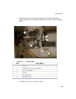
3. Slide the chamber onto the injector adapter. Close the clamp to secure the
cyclonic spray chamber assembly in place. Tighten the nut at the end of the
cyclonic spray chamber assembly. This allows you to lock in place the
downward angle of the cyclonic spray chamber. The cyclonic spray chamber
must point in a downward direction to allow the spray to flow away from the
nebulizer. This angle will remain locked even if you later remove the cyclonic
spray chamber from the instrument. Future installations will not require any
readjustments.
4. On the drain end of the cyclonic spray chamber attach Tygon tubing (Part No.
02506516). To the other end of the Tygon tubing attach the tubing coupler (Part
No. 09920186). See the following figure.
2
Cyclonic Spray Chamber Cap (opened position)
3
Cyclonic Spray Chamber (seated in cap)
4
Cyclonic Spray Chamber Cap (closed position)
Item
Description
Summary of Contents for OPTIMA 8000
Page 1: ...OPTIMA 8000 Customer Hardware and Service Guide ICP OPTICAL EMISSION Return to Document Menu...
Page 2: ......
Page 3: ...Optima 8000 Customer Hardware and Service Manual...
Page 12: ...Contents 10...
Page 18: ...16 Indicates the ON position of the main power switch Indicates alternating current...
Page 24: ...22 Figure C Location of warning labels in the sample compartment 1 2...
Page 28: ...26...
Page 29: ...Safety Practices 1...
Page 49: ...Preparing Your Laboratory 2...
Page 61: ...Preparing Your Laboratory 60...
Page 62: ...System Description 3...
Page 89: ...Installation 4...
Page 136: ...Maintenance 5...
Page 241: ...Troubleshooting 6...
Page 264: ...Error Messages 7...
Page 284: ......