


Maintenance
164
Replacing the Spray Chamber
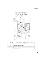
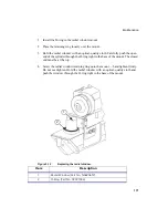
1. Orient the spray chamber so that the drain connection is facing down and
towards the rear of the sample compartment. See the following figure.
2. Check the condition of the two O-rings (Part No. 09921028) on the spray
chamber/injector adapter. If the O-rings need to be removed, carefully remove
them using a small paper clip with a hook bent on one end or a micro-spatula.
Do
not
use a knife blade because the blade will cut the O-rings and damage the
O-ring seats.
3. Firmly push the spray chamber into the spray chamber mounting block. Close
the clamp around the spray chamber until it is locked into place. The action of
closing the clamp will secure the spray chamber to the spray chamber mounting
block.
4. Make sure that the sample capillary tubing is in good condition. Replace the
tubing if necessary. Connect the sample capillary tubing to the nebulizer sample
inlet.
5. Attach the drain tubing assembly to the spray chamber drain. Check that the
drain tubing is in good condition and replace if necessary.
Connecting the Nebulizer (Neb) Tubing
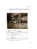
To connect the nebulizer (Neb) tubing follow these steps and refer to the next figure.
1. Connect the end of the nebulizer (NEB) argon tubing to the nebulizer end cap
and the other end to the quick disconnect by pushing the male quick connect
fitting into the quick disconnect.
2. Make sure that the teflon tubing is in good condition. Replace the tubing if
necessary. Connect the sample capillary tubing to the nebulizer sample inlet.
3. Connect the drain tubing to the spray chamber.
For instructions on connecting tubing to the peristaltic pump see the section on the
Peristaltic Pump,
later in this chapter.
Summary of Contents for OPTIMA 8000
Page 1: ...OPTIMA 8000 Customer Hardware and Service Guide ICP OPTICAL EMISSION Return to Document Menu...
Page 2: ......
Page 3: ...Optima 8000 Customer Hardware and Service Manual...
Page 12: ...Contents 10...
Page 18: ...16 Indicates the ON position of the main power switch Indicates alternating current...
Page 24: ...22 Figure C Location of warning labels in the sample compartment 1 2...
Page 28: ...26...
Page 29: ...Safety Practices 1...
Page 49: ...Preparing Your Laboratory 2...
Page 61: ...Preparing Your Laboratory 60...
Page 62: ...System Description 3...
Page 89: ...Installation 4...
Page 136: ...Maintenance 5...
Page 241: ...Troubleshooting 6...
Page 264: ...Error Messages 7...
Page 284: ......