


Installation
116
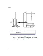
3. Connect the RS232/serial communication cable provided, between the Com 1
port on the underside of the autosampler (as shown in Figure 4-10 on page 115)
and one of the Com ports on the PC.
4. Connect the autosampler to the line power supply using the plug-in power
supply provided.
The plug-in power supply uses a wide-range input of 100-240 VAC, 50-60 Hz.
Plug the power cord into the power supply, then plug the other end of the power cord
into the power source.
5. Connect the spectrometer and other components in the system to the line power
supply.
6. Switch on all components of the system, following the routine in the manual for
your spectrometer.
Note
To avoid problems of interference caused by earth loops, always connect
the computer, printer and other components to the same phase of the line
power supply. The most convenient method is to use a multisocket outlet.
Summary of Contents for OPTIMA 8000
Page 1: ...OPTIMA 8000 Customer Hardware and Service Guide ICP OPTICAL EMISSION Return to Document Menu...
Page 2: ......
Page 3: ...Optima 8000 Customer Hardware and Service Manual...
Page 12: ...Contents 10...
Page 18: ...16 Indicates the ON position of the main power switch Indicates alternating current...
Page 24: ...22 Figure C Location of warning labels in the sample compartment 1 2...
Page 28: ...26...
Page 29: ...Safety Practices 1...
Page 49: ...Preparing Your Laboratory 2...
Page 61: ...Preparing Your Laboratory 60...
Page 62: ...System Description 3...
Page 89: ...Installation 4...
Page 136: ...Maintenance 5...
Page 241: ...Troubleshooting 6...
Page 264: ...Error Messages 7...
Page 284: ......