


Parameter Reference
15-15
AC10 Inverter
Function
Code
Function
Definition
Setting Range
Mfr’s Value
Change
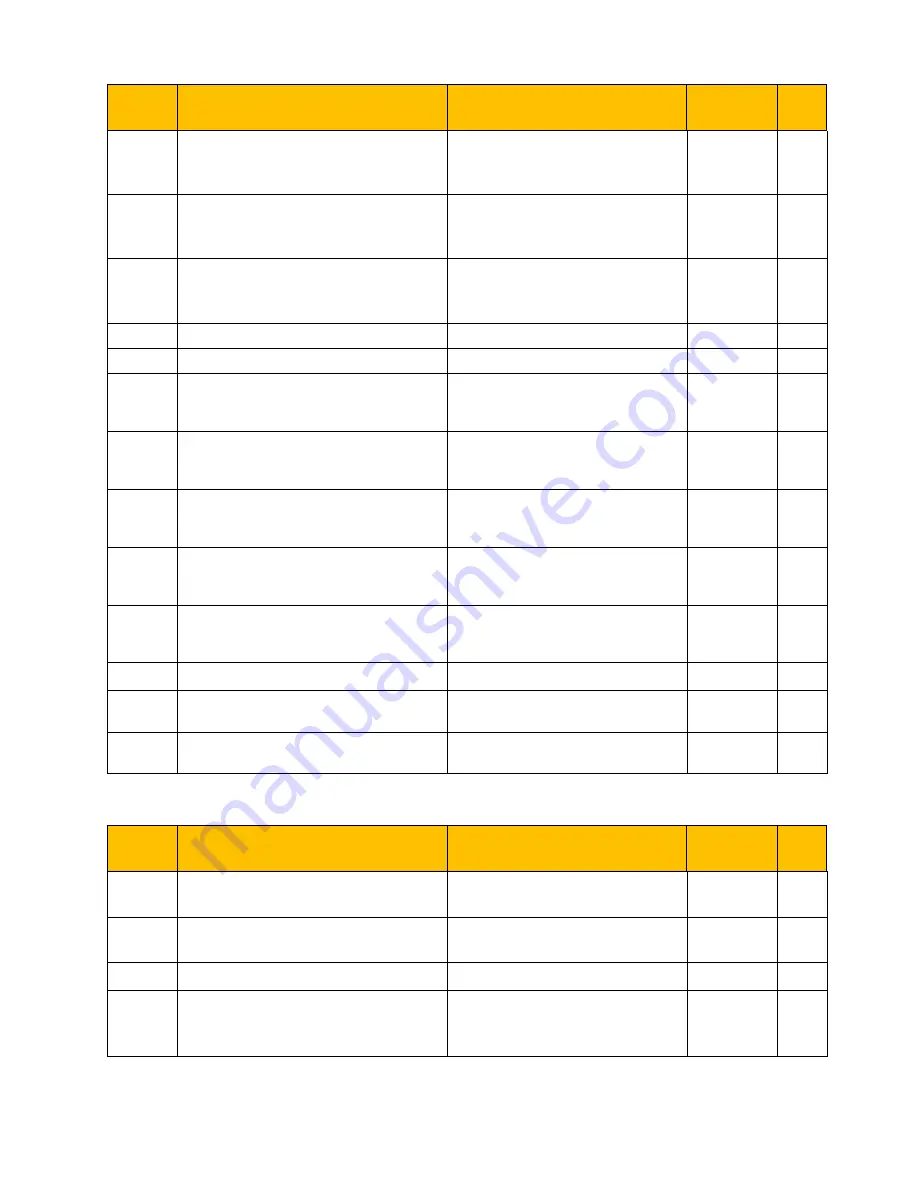
F814
Rotary Speed Loop KI1
0.01
~
2.00 (for 22kw and below
22kw)
0.01~10.00 (For above 22kw)
Subject to
inverter
model
○
√
F815
Rotary Speed Loop KP2
0.01
~
20.00 (for 22kw and below
22kw)
1~100 (For above 22kw)
Subject to
inverter
model
○
√
F816
Rotary Speed Loop KI2
0.01
~
2.00 (for 22kw and below
22kw)
0.01~10.00 (For above 22kw)
Subject to
inverter
model
○
√
F817
PID Switching Frequency 1
0~F111
5.00
√
F818
PID Switching Frequency 2
F817~F111
50.00
√
F819~
F860
Reserved
Subject to
inverter
model
√
F870
PMSM back electromotive force (mV/rpm) 0.1
~
999.9
Subject to
inverter
model
○
F871
PMSM D-axis inductance (mH)
0.01
~
655.35
Subject to
inverter
model
○
F872
PMSM Q-axis inductance (mH)
0.01
~
655.35
Subject to
inverter
model
○
F873
PMSM stator resistance
(
Ω
)
0.001
~
65.535
Subject to
inverter
model
○
F876
PMSM injection current without load (%)
0.0
~
100.0
20.0
×
F877
PMSM injection current compensation
without load (%)
0.0
~
50.0
0.0
×
F878
PMSM cut-off point of injection current
compensation without load (%)
0.0
~
50.0
10.0
×
Communication parameter: F900-F930
Function
Code
Function
Definition
Setting Range
Mfr’s Value
Change
F900
Communication Address
1~255: single inverter address
0: broadcast address
1
√
F901
Communication Mode
1: ASCII
2: RTU
1
○
√
F902
Stop byte
1
~
2
2
√
F903
Parity Check
0: Invalid
1: Odd
2: Even
0
√
www.comoso.com
Summary of Contents for 10G-11-0015 Series
Page 2: ...www comoso com...


