384
JAN 2006
Ver. 5.2
DP-3510/3520/3530/4510/4520/4530/6010/6020/6030
8.28. Installing the Punch Unit (DA-SP31)
8.28.1. Contents
Note:
1. The part number may differ depending on the Destination.
2. Refer to the Parts List in the Parts Manual.
8.28.2. Installation
CAUTION!
Turn the Power Switch on the Left Side and the Main Power Switch on the Back of the
machine to the OFF position, and then unplug the AC Power Cord before beginning
installation.
Qty.
Description
Part No.
Remarks
1
Punch Unit
See Note
1
Punch Lower Cover
4A1-8409-000
1
Punch Relay Harness
FF3-4067-000
1
Upper Cover Guide
4A1-8408-000
1
Guide Plate (Long)
4B1-0949-000
1
Jam Removal Instructions Label
FB5-5924-000
2
Shoulder Screw (Silver)
See Note
2
Stepped Mounting Screw (Silver)
See Note
1
Black Screw (M4 x 6)
See Note
2
Silver Screw (M4 x 12)
See Note
1
Installation Instructions
DZSM000567
This document
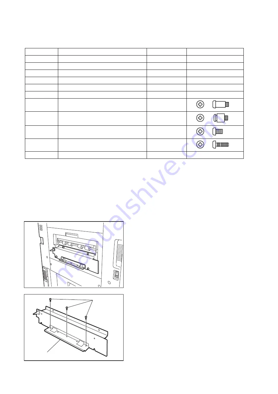
Preparing the Host Machine for Installation
(1) Remove the bottom 3 Screws, and remove
Guide Plate (Short).
(1)
Guide Plate (Short)
Summary of Contents for Workio DP-3510
Page 4: ...4 Beispiel DP 6530 4530 6030 Hinweis...
Page 424: ...424 JAN 2006 Ver 5 2 DP 3510 3520 3530 4510 4520 4530 6010 6020 6030...
Page 425: ...425 JAN 2006 Ver 5 2 DP 3510 3520 3530 4510 4520 4530 6010 6020 6030...
Page 474: ...474 JAN 2006 Ver 5 2 DP 3510 3520 3530 4510 4520 4530 6010 6020 6030 memo...
Page 842: ...memo...
Page 858: ...DZZSM00298...


