Part Description
© Panasonic Industrial Devices SUNX Co., Ltd. 2020
18
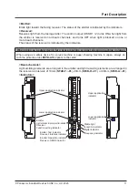
●
Emitter/receiver common
Name
Function
Line synchronization
Optical synchronization
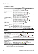
Upper application indicator
(Blue / Red / Green / Orange)
(Note 1)
<When beam axis alignment mode is set>
Control output (OSSD 1 / 2) ON: Lights blue “
”
When top end beam channel receives light: Lights red “ ”
When top end beam channel is blocked: Turns OFF
<When application mode is set>
When application indicator input 1 is ON: Lights green “
”
When application indicator input 2 is ON: Lights red “
”
When application indicator input 1 / 2 are ON: Lights orange “
”
When application indicator input 1 / 2 are OFF: Turns OFF
Lower application indicator
(Blue / Red / Green / Orange)
(Note 1)
<When beam axis alignment mode is set>
Control output (OSSD 1 / 2) ON: Lights blue “
”
When bottom end beam channel receives light: Lights red “ ”
When bottom end beam channel is blocked: Turns OFF
<When application mode is set>
When application indicator input 1 is ON: Lights green “
”
When application indicator input 2 is ON: Lights red “
”
When application indicator input 1 / 2 are ON: Lights orange “
”
When application indicator input 1 / 2 are OFF: Turns OFF
Stable light reception indicator
(Green / Orange)
When light reception is stable: Lights green “ ”
When light reception is unstable: Lights orange “ ”
When light is blocked: Turns OFF
Digital indicator
(Green / Yellow)
Received
light intensity
(Green)
Light intensity / Level 3: Lights green “ ”
Light intensity / Level 2: Lights green “ ”
Light intensity / Level 1: Lights green “ ”
When light is blocked: Turns OFF
Error (Yellow)
Normal operation: Turns OFF, Error: Yellow number blinks or lights “
”
Polarity
(Yellow)
When PNP output is set: Lights yellow “ ” (only during startup)
When NPN output is set: Lights yellow “ ” (only during startup)
Frequency indicator (Orange)
-
When frequency 1 is set: Lights orange “
”
When frequency 2 is set: Lights orange “
”
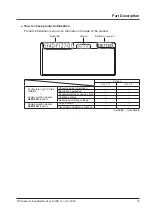
●
Emitter
Name
Function
Line synchronization
Optical synchronization
Light emission intensity control
indicator (Orange) [CTRL]
Short mode: Turns OFF, Long mode: Lights orange “
”
Test indicator (Orange) [TEST]
During test: Lights orange “
”, Normal operation: Turns OFF
Operation indicator
(Red / Green) [OP]
Control output (OSSD 1 / 2) OFF:
Lights red “
”
Control output (OSSD 1 / 2) ON:
Lights green “
”
Normal operation: Lights green “
”
Error: Lights red “
”
●
Receiver
Name
Function
Line synchronization
Optical synchronization
Function setting indicator
(Orange) [FUNC]
Communication module connected: Blinks orange “
”
Interlock indicator (Yellow)
[LOCK]
Interlock activated: Lights yellow “
”, All other times: Turns OFF
OSSD indicator (Red / Green)
[OSSD]
Control output (OSSD 1 / 2) OFF: Lights red “
”
Control output (OSSD 1 / 2) ON: Lights green “
”
Notes: 1) In the case of optical synchronization, the upper application indicator and lower application indicator on
the emitter remain OFF.
2) Names in brackets [ ] are names that are indicated on the device.
Summary of Contents for SF4D-*-01 Series
Page 2: ... Panasonic Industrial Devices SUNX Co Ltd 2020 2 MEMO ...
Page 6: ... Panasonic Industrial Devices SUNX Co Ltd 2020 6 MEMO ...
Page 120: ...Functions Panasonic Industrial Devices SUNX Co Ltd 2020 120 MEMO ...
Page 134: ...Troubleshooting Panasonic Industrial Devices SUNX Co Ltd 2020 134 MEMO ...
Page 168: ... Panasonic Industrial Devices SUNX Co Ltd 2020 168 MEMO ...

