Troubleshooting
© Panasonic Industrial Devices SUNX Co., Ltd. 2020
131
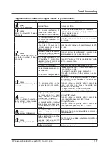
Cause
Remedy
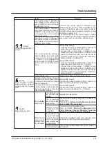
[“
”, “
” blinks]
Control output (OSSD 1 /
2) error.
The control output 1 (OSSD 1)
wire (black) or the control out-
put 2 (OSSD 2) wire (white) is
shorted to 0V or +V.
Connect the control output 1 (OSSD 1) wire
(black) and the control output 2 (OSSD 2) wire
(white) to the safety relay unit, external device
(forcible guide relay or magnetic contactor), safety
controller, or safety PLC.
The current values of the control output 1 (OSSD
1) wire (black) and the control output 2 (OSSD 2)
wire (white) must be within the specified range.
The control output 1 (OSSD 1)
wire (black) and control output 2
(OSSD 2) wire (white) are short
-
ed to each other, or to another
input / output wire.
Excessive current is flowing in
the control output 1 (OSSD 1)
wire (black) or control output 2
(OSSD 2) wire (white).
The output polarity setting /
lockout release input wire (pale
blue), and the control output
1 (OSSD 1) wire (black) and
control output 2 (OSSD 2) wire
(white) are not connected cor-
rectly.
<Using PNP output>
• Connect the output polarity setting / lockout re-
lease input wire (pale blue) to 0V (blue).
•
Connect the control output 1 (OSSD 1) wire
(black) and the control output 2 (OSSD 2) wire
(white) to the safety relay unit, external device
(forcible guide relay or magnetic contactor),
safety controller, or safety PLC.
<Using NPN output>
• Connect the output polarity setting / lockout re-
lease input wire (pale blue) to + V (brown).
•
Connect the control output 1 (OSSD 1) wire
(black) and the control output 2 (OSSD 2) wire
(white) to the safety relay unit, external device
(forcible guide relay or magnetic contactor),
safety controller, or safety PLC.
Output circuit error.
Output circuit damage. Replace the device.
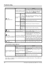
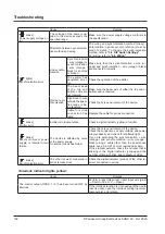
[“ ” blinks]
Error in wiring of output
polarity setting / lockout
release input wire (pale
blue).
Output polarity setting / lockout
release input wire (pale blue)
is broken or shorted to another
input / output wire.
Incorrect connection of output
polarity setting / lockout release
input wire (pale blue) of receiver
side of emitter / receiver.
<Using PNP output>
Connect the output polarity setting / lockout re-
lease input wire (pale blue) to 0V (blue).
<Using NPN output>
Connect the output polarity setting / lockout re-
lease input wire (pale blue) to + V (brown).
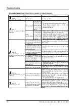
[“ ” blinks]
External device error.
When a safety
relay is used
The safety re-
lay contact has
welded.
Replace the safety relay.
T h e r e s p o n s e
time of the safety
relay is slow.
Replace with a safety relay with a suitable re-
sponse time.
Refer to
“3-6 External Device Monitor Function
(8-core cable, 12-core cable)”
S a f e t y r e l a y
contact "b" is not
connected.
Correctly connect the safety relay.
Refer to
“2-5-7 Wiring Configuration for
Valid External Device Monitor Function
(Example of Control Category 4 Wiring)”
.
When the ex-
ternal device
monitor func-
tion is invalid.
The auxiliary out-
put wire (red) and
external device
monitor input wire
(pale purple) are
not connected.
Connect the auxiliary output wire (red) and exter-
nal device monitor input wire (pale purple).
Auxiliary output does
not operate correctly.
Check if the auxiliary output wire (red) is broken or
has shorted.
Summary of Contents for SF4D-*-01 Series
Page 2: ... Panasonic Industrial Devices SUNX Co Ltd 2020 2 MEMO ...
Page 6: ... Panasonic Industrial Devices SUNX Co Ltd 2020 6 MEMO ...
Page 120: ...Functions Panasonic Industrial Devices SUNX Co Ltd 2020 120 MEMO ...
Page 134: ...Troubleshooting Panasonic Industrial Devices SUNX Co Ltd 2020 134 MEMO ...
Page 168: ... Panasonic Industrial Devices SUNX Co Ltd 2020 168 MEMO ...

