


5-5
5.3 Procedure for Connecting and Setting Up
The connection and setting procedure of teh remote I/O system [MEWNET-F] is described as follows.
5.3.1 Preparation
Turn OFF all power supply to devices.
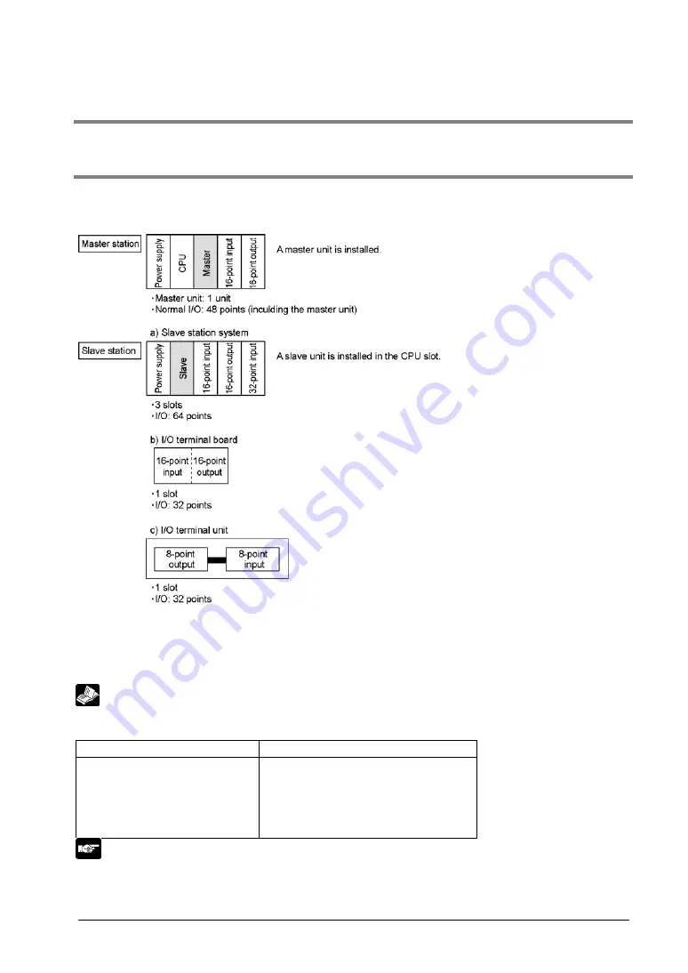
Configure the master stations and slave stations.This section describes an example of the procedure
using the following 4 stations.
Install each station at prescribed positions.
Configure a system which perform the remote I/O control with a master unit, 3 stations, 5 slots and 128
I/O points.
This CPU controls the normal I/O area and remote I/O area with totally 8 slots and 176 I/O points.
Reference:
For information on the onstallation of master station system and slave station system,
<FP3/FP10SH/FP10S Hardware Manual ARCT1F300E-1>
Master Station (Master Unit)
Max. 4 units/1 CPU
Slave station
Per 1 master unit (1 path)
- Max. 32 stations
- Max. 64 slots
Per 1 CPU
- Max. 128 slots
Note:
If the system is not properly configured, an error will be detected when the power turned on.
[E35] There are units which cannot be installed on a slave station system.
[E36] Number of slots or number of I/O points is out of range.
Summary of Contents for MEWNET-F
Page 9: ...Chapter 1 Functions and Restrictions of the Unit ...
Page 19: ...Chapter 2 Part Names and Functions ...
Page 40: ...2 22 ...
Page 41: ...Chapter 3 Unit Specifications ...
Page 52: ...3 12 ...
Page 53: ...Chapter 4 Installation and Wiring ...
Page 62: ...4 10 ...
Page 63: ...Chapter 5 Connection for the Remote I O System ...
Page 75: ...Chapter 6 Remote I O Map ...
Page 84: ...6 10 ...
Page 85: ...Chapter 7 Operation Modes for Controlling MEWNET F ...
Page 97: ...Chapter 8 Control by MEWNET F ...
Page 108: ...8 12 Flowchart ...
Page 110: ...8 14 ...
Page 111: ...Chapter 9 Troubleshooting ...
Page 120: ...9 10 ...
Page 121: ...9 11 9 5 2 When the ALARM LED is ON ...
Page 122: ...9 12 9 5 3 When the Communication LED on the Master Unit does Not Flash Normally ...
Page 123: ...9 13 When the COMM LED is OFF ...
Page 124: ...9 14 When the COMM LED is ON ...
Page 125: ...9 15 9 5 4 When the Communication LED on a Slave Station does Not Flash Normally ...
Page 126: ...9 16 When the COMM LED is OFF ...
Page 127: ...9 17 When the COMM LED is ON ...
Page 128: ...9 18 9 5 5 When the CPU does Not Operate ...
Page 129: ...9 19 9 5 6 When the Input Output Function of a Slave Station does Not Work ...
Page 130: ...9 20 9 5 7 When the Memory Access Function for the Advanced Unit s Memory does Not Work ...
Page 134: ...9 24 ...
Page 135: ...Chapter 10 Dimensions ...
Page 136: ...10 2 10 1 FP2 Multi wire Link Unit AFP2720 10 2 FP3 Remote I O Master Unit AFP3742 ...
Page 137: ...10 3 10 3 FP2 Remote I OSlave Unit AFP2745 10 4 FP3 Remote I OSlave Unit AFP3745 ...
Page 141: ...10 7 10 8 FP0 I O Link Unit AFP0732 ...
Page 142: ...10 8 ...
Page 143: ...Chapter 11 Appendix 1 I O Link With FP1 ...
Page 147: ...11 5 11 3 Part Names and Functions ...
Page 159: ...Chapter 12 Appendix 2 I O Link With FP0 ...
Page 164: ...12 6 ...
Page 166: ......
Page 167: ......
Page 168: ...FAF 35E 1 200803 http www mew co jp ac e fasys 2008 ...


