


3-10
3.5 Communication Time
The communication time regarding the remote I/O system [MEWNET-F] control is described.
3.5.1 Remote I/O Scan Time [T
R
]
The remote I/O scan time represents the time it takes the master unit, with respect to the connected
slave stations, to send all the output data which has been written to the buffer memory in the master unit
and write all the input data received from the slave stations to the buffer memory in the master unit.
T
R
=0.8+0.85×n+0.55×N+0.13×W (ms)
n
: No. of I/O terminal boards
N
: No. of slave units
W
: No. of I/O words used by the remote I/O system
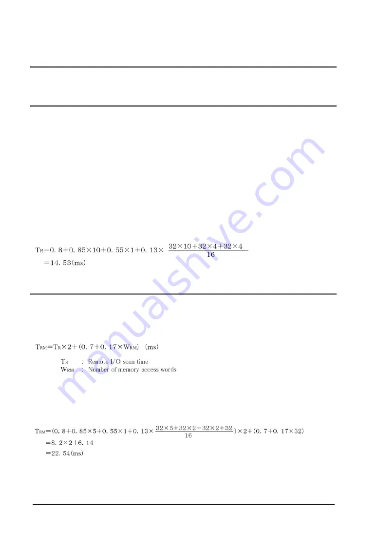
[Example]
When 10 FP I/O terminal boards (16 input points and 16 output points) and a salve station (connected to
one slave unit, 4 input units (32 input point), 4 output unit (32 output points)] are connected.
3.5.2 Remote I/O Memory Access Time [T
RM
]
The remote I/O memory access time represents the time it takes the master unit to receive the memory
access end message from the slave unit after it receives a memroy access request from the CPU.
As this value is a guide, confirm on the actual units.
[Example]
When 5 I/O terminal boards (16 input points and 16 output points each) and a slave station [connected
to 1 slave unit, 2 input units (32 input points), 2 output unit (32 output points) and 1 advanced unit
(occupies 32 points)] are connected and a 32-word memory access is performed with an advanced unit.
Summary of Contents for MEWNET-F
Page 9: ...Chapter 1 Functions and Restrictions of the Unit ...
Page 19: ...Chapter 2 Part Names and Functions ...
Page 40: ...2 22 ...
Page 41: ...Chapter 3 Unit Specifications ...
Page 52: ...3 12 ...
Page 53: ...Chapter 4 Installation and Wiring ...
Page 62: ...4 10 ...
Page 63: ...Chapter 5 Connection for the Remote I O System ...
Page 75: ...Chapter 6 Remote I O Map ...
Page 84: ...6 10 ...
Page 85: ...Chapter 7 Operation Modes for Controlling MEWNET F ...
Page 97: ...Chapter 8 Control by MEWNET F ...
Page 108: ...8 12 Flowchart ...
Page 110: ...8 14 ...
Page 111: ...Chapter 9 Troubleshooting ...
Page 120: ...9 10 ...
Page 121: ...9 11 9 5 2 When the ALARM LED is ON ...
Page 122: ...9 12 9 5 3 When the Communication LED on the Master Unit does Not Flash Normally ...
Page 123: ...9 13 When the COMM LED is OFF ...
Page 124: ...9 14 When the COMM LED is ON ...
Page 125: ...9 15 9 5 4 When the Communication LED on a Slave Station does Not Flash Normally ...
Page 126: ...9 16 When the COMM LED is OFF ...
Page 127: ...9 17 When the COMM LED is ON ...
Page 128: ...9 18 9 5 5 When the CPU does Not Operate ...
Page 129: ...9 19 9 5 6 When the Input Output Function of a Slave Station does Not Work ...
Page 130: ...9 20 9 5 7 When the Memory Access Function for the Advanced Unit s Memory does Not Work ...
Page 134: ...9 24 ...
Page 135: ...Chapter 10 Dimensions ...
Page 136: ...10 2 10 1 FP2 Multi wire Link Unit AFP2720 10 2 FP3 Remote I O Master Unit AFP3742 ...
Page 137: ...10 3 10 3 FP2 Remote I OSlave Unit AFP2745 10 4 FP3 Remote I OSlave Unit AFP3745 ...
Page 141: ...10 7 10 8 FP0 I O Link Unit AFP0732 ...
Page 142: ...10 8 ...
Page 143: ...Chapter 11 Appendix 1 I O Link With FP1 ...
Page 147: ...11 5 11 3 Part Names and Functions ...
Page 159: ...Chapter 12 Appendix 2 I O Link With FP0 ...
Page 164: ...12 6 ...
Page 166: ......
Page 167: ......
Page 168: ...FAF 35E 1 200803 http www mew co jp ac e fasys 2008 ...


