218
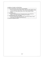
Screen Description
Entry Displays the event number.
Time Displays the time when the event occurred, or the time accumulated after
boot if the clock is not set.
Event Displays the description of the event caused to the Switching Hub.
System Cold Start
Indicates that this Switching Hub started.
Login from console
Indicates a login from the console port.
Login from telnet,
xxx.xxx.xxx.xxx
Indicates a login via Telnet.
Configuration changed
Indicates that the configuration was changed.
Runtime code changes
Indicates that the firmware was changed.
Configuration file upload
Indicates that the configuration file was
transferred to the TFTP server.
Configuration file
download
Indicates that the configuration file was
transferred from the TFTP server.
(Bridge)Topology Change Displays that the spanning tree topology was
changed.
Reboot: Normal
Indicates that this Switching Hub rebooted.
Reboot: Factory Default
Indicates that this Switching Hub rebooted to
return settings to factory default.
Reboot: Factory Default
Except IP
Indicates that this Switching Hub rebooted to
return settings except the IP address to factory
default.
Not authorized! (IP:
xxx.xxx.xxx.xxx)
Indicates that an unauthorized manager accessed
by SNMP.
SNTP first update to
yyyy/mm/dd hh:mm:ss
Indicates that time data was obtained by
accessing the SNTP server.
Found other multicast
router. Stopped querier
function.
Indicates that the function was stopped because
another IGMP querier exists.
Other multicast router is
expired. Restarted querier
function.
Indicates that the function was restarted because
another IGMP querier no longer exists.
FAN status changed from
good to failed.
Indicates that a fan problem occurred.
Temperature over
threshold.
Indicates that the internal temperature exceeded
the threshold.
Temperature under
threshold.
Indicates that the internal temperature decreased
below the threshold.
! Stus: xxxxxxxx IP: x Code:
x Add: xxxxxxxx
! Tsk: "xxxx" P:xxxxxxxxx
Pri: xx
Indicates the system information when an
exception was raised.
Port-
xx
Link-up
Indicates that the port was linked up.
Port-
xx
Link-down
Indicates that the port was linked down.
Port-
xx
Power ON
notification
Indicates that the power supply to the target
port is turned on.
Port-
xx
Power OFF
notification
Indicates that the power supply to the target
port is turned off.
Summary of Contents for M24PWR
Page 26: ...26 ...
Page 32: ...32 ...
Page 45: ...45 ...
Page 65: ...65 ...
Page 77: ...77 setting and the management VLAN status of VLAN ID 1 is UP ...
Page 92: ...92 Press S Q Return to the previous menu ...
Page 94: ...94 ...
Page 118: ...118 Q Return to the previous menu ...
Page 121: ...121 ...
Page 126: ...126 ICMP Type Displays the ICMP type ...
Page 152: ...152 Threshold Displays the threshold of the number of packets per second ...
Page 169: ...169 Fig 4 7 49 Display of values accumulated after resetting the counters ...
Page 181: ...181 Q Return to the previous menu ...
Page 207: ...207 Q Return to the previous menu ...
Page 228: ...228 RSTP MIB IEEE 802 1w IEEE8021 PAE MIB IEEE802 1X IEEE8023 LAG MIB IEEE 802 3ad ...
Page 233: ...233 IEEE 802 3af standard ...


