23
4
4
.
.
3
3
.
.
B
B
a
a
s
s
i
i
c
c
O
O
p
p
e
e
r
r
a
a
t
t
i
i
o
o
n
n
s
s
o
o
n
n
t
t
h
h
e
e
S
S
c
c
r
r
e
e
e
e
n
n
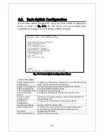
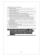
The console screen of the Switching Hub is organized as follows:
Fig.
4-3-1 Screen structure
Screen Description
1. Title
The title of this screen. Displays "Local Management System"
while being accessed via console. Displays "Remote
Management System" while being accessed via Telnet.
2. Previous menu
name
Displays the name of the parent menu. Entering the "Q"
command opens the parent menu screen.
3. Current menu name Displays the name of the current screen.
4. Configuration
Displays the current configuration.
5. Command
Displays the commands available on this screen. Available
commands differ on each screen. Select a command from the
list.
6. Prompt
Changes as you enter a command, indicating what you need to
enter next. Follow this instruction.
7. Command entry line Enter a command or settings.
8. Explanation
Displays the explanation and/or status of this screen. Also,
displays an entry error message if applicable.
All operations on this screen are done by entering letters. Using a cursor or
other operations are not available. Available commands (letters) differ on
each screen. They are shown in the command section. One letter of each
command is enclosed in square brackets ([]). Enter this letter to enter the
PN23249K/PN23249A Local Management System
Basic Switch Configuration -> System Admin. Configuration Menu
Description: Switch-M24PWR
Object ID: 1.3.6.1.4.1.396.5.4.1.19
Name:
Location:
Contact:
-------------------------------- <COMMAND> -----------------------------------
Set System [N]ame
Set System [L]ocation
Set System [C]ontact Information
[Q]uit to previous menu
Command>
Enter the character in square brackets to select option
6. Prompt
7. Command entry
l
4. Configuration
5. Command
8. Explanation
2. Previous menu
1. Title
3. Current menu
Summary of Contents for M24PWR
Page 26: ...26 ...
Page 32: ...32 ...
Page 45: ...45 ...
Page 65: ...65 ...
Page 77: ...77 setting and the management VLAN status of VLAN ID 1 is UP ...
Page 92: ...92 Press S Q Return to the previous menu ...
Page 94: ...94 ...
Page 118: ...118 Q Return to the previous menu ...
Page 121: ...121 ...
Page 126: ...126 ICMP Type Displays the ICMP type ...
Page 152: ...152 Threshold Displays the threshold of the number of packets per second ...
Page 169: ...169 Fig 4 7 49 Display of values accumulated after resetting the counters ...
Page 181: ...181 Q Return to the previous menu ...
Page 207: ...207 Q Return to the previous menu ...
Page 228: ...228 RSTP MIB IEEE 802 1w IEEE8021 PAE MIB IEEE802 1X IEEE8023 LAG MIB IEEE 802 3ad ...
Page 233: ...233 IEEE 802 3af standard ...


