background image

Appendix B. Aurora H2O Ethernet Operation

24

Aurora H2O User’s Manual

B.0.1 MODBUS/RTU

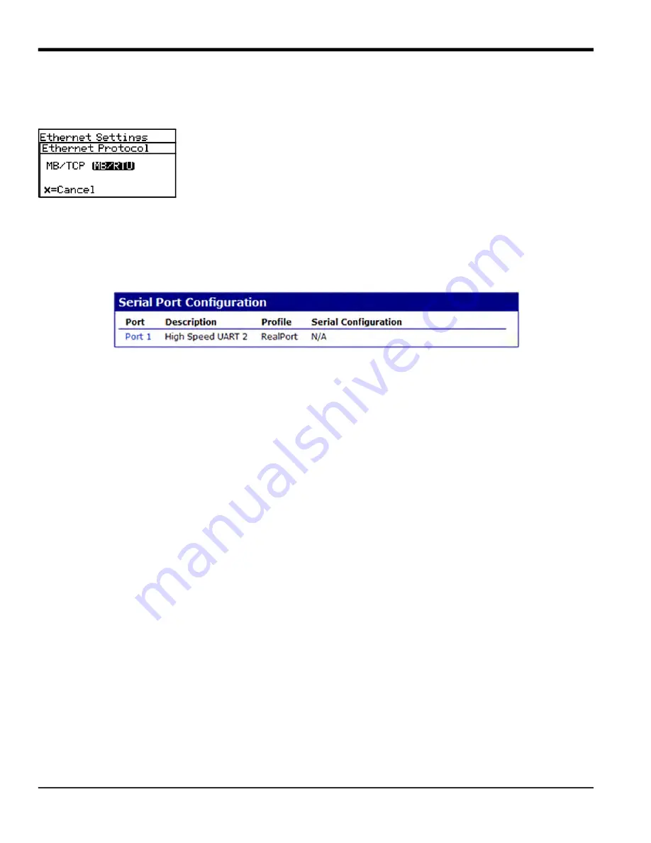
To change the default 

MB/TCP

 Ethernet protocol and use the 

MB/RTU

 protocol instead, follow the instructions in this 

section.

Select 

MODBUS/RTU (MB/RTU)

 from the Aurora H2O menu (

Main Menu, Settings…, 

Ethernet…, Protocol

).

To use Modbus/RTU over Ethernet, the Ethernet module must also be configured as 

follows:

1.

Log in to the web user interface. Either the root account or an operator account may be used to configure the 

module.

2. Choose 

Serial Ports

 from the 

Configuration Menu

. Verify that 

RealPort

 is selected as the 

Profile

 (see 

Figure 112


below).

3. Click on the 

Port 1

 link to display the current 

Profile

.

Figure 112: MB/RTU Serial Port 1 Profile

4.

If the information displayed is not correct, change the profile as required.

Summary of Contents for Aurora H2O

Page 1: ...panametrics com 910 317 B August 2022 Aurora H2O User s Manual...

Page 2: ......

Page 3: ...ns one or more registered trademarks of Baker Hughes Company and its subsidiaries in one or more countries All third party product and company names are trademarks of their respective holders Aurora H...

Page 4: ...ii no content intended for this page...

Page 5: ...5 2 7 1 Description 5 2 7 2 Installation 5 2 7 3 Setting the Pressure 13 2 8 Making Electrical Connections 14 2 9 Specific Conditions of Use 18 Chapter 3 Operation and General Programming 3 1 Using th...

Page 6: ...otocol 2 4 1 5 Setting the Network ID 2 4 1 6 Adjusting the Response Delay 3 4 1 7 Serial Port Test 3 4 2 Ethernet Settings 4 4 2 1 Connection to the Internet WAN 4 4 2 2 Default Passwords 4 4 2 3 Con...

Page 7: ...s 1 6 2 Cleaning the Mirror 1 6 2 1 Instructions for Optical Absorption Cell Style 1 3 6 2 2 Instructions for Optical Absorption Cell Style 2 8 6 3 Replacing the Filter Element 12 Chapter 7 Troublesho...

Page 8: ...Contents vi Aurora H2O User s Manual B 4 Communicating by MODBUS via Ethernet 23 B 4 1 MODBUS TCP 23 B 0 1 MODBUS RTU 24 B 1 Using TELNET for Configuration 25 B 1 Using the MS Windows Telnet Client 26...

Page 9: ...at provides a deeper understanding of the situation but is not essential to the proper completion of the instructions IMPORTANT These paragraphs provide information that emphasizes instructions that a...

Page 10: ...cable to the auxiliary equipment Examples include safety glasses protective headgear safety shoes etc Unauthorized Operation Make sure that unauthorized personnel cannot gain access to the operation o...

Page 11: ...t could impact health and the environment In order to avoid the dissemination of those substances in our environment and to diminish the pressure on the natural resources we encourage you to use the a...

Page 12: ...Chapter x Aurora H2O User s Manual no content intended for this page...

Page 13: ...entry into the energy grid CLASS 1 LASER PRODUCT 1 2 Features Optical response 2 seconds after flow cell is purged No cross sensitivity to glycols or amines Direct readout in lbs mmscf mg m3 or ppm R...

Page 14: ...n the Beer Lambert Law where A Absorbance I Light intensity transmitted through a sample gas Io Incident light intensity S Absorption coefficient L Absorption path length a constant N Concentration of...

Page 15: ...klit three parameter LCD display provides digital indication of user programmable parameters The Aurora H2O has three user programmable 4 20 mA analog outputs and two programmable digital ports that m...

Page 16: ...Aurora H2O User s Manual 1 3 System Components cont Note Refer to Figure 2 below and Table 1 on page 6 to identify your Aurora components Figure 2 Aurora H2O System Assembly with Optional USA CAN Heat...

Page 17: ...Features and Capabilities 1 3 System Components cont Note Refer to Figure 3 below and Table 1 on page 6 to identify your Aurora components Figure 3 Aurora H2O System Assembly with Optional EU ATEX Hea...

Page 18: ...wer and Signal I O Conduit 2 Display and Magnetic Stylus Keypad 3 Wiring Terminals 4 Isolation Valve needle valve 5 Membrane Filter 6 Membrane Filter Drain Fast Loop Vent 7 Pressure Regulator w 0 10 p...

Page 19: ...insertion filter also is equipped with a pressure regulator which functions to reduce the pressure If it is not possible to install the insertion filter consult BH application engineers for informatio...

Page 20: ...BROWN BLUE GREEN YELLOW HEATER CONNECTION J1 16 AWG BROWN WIRE 2 STRIP 1 4 NEUTRAL LINE 230 VAC 120 VAC CUSTOMER CABLE CABLE TO HEATER CABLE TO THERMOSTAT Cable Function Conductor Color J Box Terminal...

Page 21: ...1 4 2 Accuracy Parts Per Million By Volume 1 of reading or 2 ppmv whichever is greater for 1000 ppmv 5 of reading For CO2 applications 3 of reading or 5 ppmv For H2 recycle applications 1 of reading o...

Page 22: ...pressure available with the application of additional sampling system components 1 4 5 Flow Rate Sample Cell Flow Rate 10 to 60 SLH 0 4 to 2 SCFH 30 SLH 1 SCFH nominal By Pass Fast Loop 5 to 10X of f...

Page 23: ...66 Net Weight 45 kg 100 lb Dimensions H x L x W 841 2 mm x 461 mm x 332 3 mm 33 12 in x 18 31 in x 13 08 in 1 4 8 Temperature Operating 20 to 65 C 4 to 149 F Storage 20 to 70 C 4 to 158 F Optional Hea...

Page 24: ...Chapter 1 Features and Capabilities 12 Aurora H2O User s Manual...

Page 25: ...temperature above the dew point An optional heater installed within the enclosure is also available 2 2 Bill of Materials The following items should have been received with your shipment 2 3 Unpacking...

Page 26: ...2 Avoid unnecessarily long lengths of sample transport tubing to minimize transport time to the analyzer 3 Avoid dead legs in the sample transport tubing to minimize the possibility of liquid build u...

Page 27: ...t or Armored Cable suitable for area rating Sample Transport Line Minimize distance Tie to Vent Flare Do not restrict Install at a 12 o clock or optionally 3 o clock or 9 o clock position on a horizon...

Page 28: ...cate the circuit breaker or power switch near the electronics console IMPORTANT Installation must be done in accordance with the National Electrical Code the Canadian Electric Code and or any other ap...

Page 29: ...ncludes a foot valve so that once installed the assembly can be removed from a line under pressure for membrane filter replacement as needed Figure 9 Insertion Probe Regulator Note A 29 32 0 907 inch...

Page 30: ...xtreme upper position Apply thread sealant to the threaded area below vertical slots in the threads see Figure 11 below Do not allow the thread sealant to enter the slot as it may interfere with the m...

Page 31: ...o let The minimum ID of the thread o let is 0 91 Figure 12 Inserting Housing into Pipeline 3 Using a wrench on the wrench flats turn the housing until it is secure and sealed see Figure 13 below This...

Page 32: ...urface until their tips are firmly set into the thread o let s upper surface see Figure 15 below Figure 15 Tightening the Allen Screws The housing is now installed The locking mechanism should prevent...

Page 33: ...crew 2 Rotate the pressure adjustment screw on the pressure regulator fully counterclockwise until it rotates freely Close the isolation ball valve see Figure 17 below Figure 17 Rotating the Pressure...

Page 34: ...he probe only enough to thread the insertion nut one complete turn of thread engagement Figure 18 Installing the Probe 4 Thread the insertion nut down by hand lowering the probe until the insertion wa...

Page 35: ...Figure 20 below Figure 20 Rotating the Probe 6 Loosen the insertion nut until it is above the top of the second vertical slot see Figure 21 below The probe should not rise to the top of the second ver...

Page 36: ...Tighten the insertion nut by hand until it is against the insertion washer again Using a wrench tighten the insertion nut against the insertion washer so that the pins are at the bottom the second ve...

Page 37: ...The optional pipeline insertion membrane liquid separator pressure regulator is the FIRST STAGE pressure reduction of the system when used Depending upon your source pressure you should step down the...

Page 38: ...uirements for wiring the unit Figure 24 Conduit Inlet Ports Note Use one conduit inlet for power Use the two other conduit inlets for input output as needed All unused conduit inlet ports should be se...

Page 39: ...designated as SCADA Port 2 is designated as SERVICE For operation on RS 485 2 wire half duplex bus attach the RS 485 to and the RS 485 to Per Modbus IDA specifications a third common conductor must a...

Page 40: ...below All other units must have jumpers J15 and J16 in positions 2 3 default setting from the factory For more details on RS 485 wiring or operation refer to TIA EIA 485 A Specification Figure 27 RS...

Page 41: ...e table below depending on the cable used Figure 29 Ethernet Terminal Block 7 For connection to a PC to interface with AuroraView software you may use the supplied 704 688 cable RS 232 w SUB D 9 conne...

Page 42: ...ith an optional electrical heater there are two possible configurations USA CAN or EU Connect the AC power using a separate conduit from the power for the Aurora H2O analyzer The heater is equipped wi...

Page 43: ...alled laser head assembly bolts are inaccessible from the outside 3 Consult the manufacturer for genuine replacement flange fasteners 5 16 inch 24 x 1 1 4 inch 18 8 stainless steel socket head cap bol...

Page 44: ...Chapter 2 Installation 20 Aurora H2O User s Manual...

Page 45: ...Aurora H2O User s Manual 21 33 12 26 16 24 26 95 15 66 1 622 10 92 18 31 10 24 13 08 125 9 29 TYP 3 18 TYP 24 91 Figure 32 Aurora H2O Outline and Mounting ref dwg 712 1456...

Page 46: ...Aurora H2O User s Manual 22 Figure 33 Aurora H2O Electronic Assembly Wiring Diagram ref dwg 702 8976...

Page 47: ...Aurora H2O User s Manual 28...

Page 48: ...en the bypass gas metering valve item 2 1 4 turn counter clockwise 6 Fully open the sample gas metering valve item 3 by turning it fully counter clockwise 7 Slowly open the supply gas isolation valve...

Page 49: ...r item 6 should be turned fully counter clockwise 2 Confirm that there are no flow restrictions downstream of the analyzer sample outlet The maximum outlet back pressure should be 10 psig 69 kPa 3 Sta...

Page 50: ...amming 3 2 Sample System cont Figure 34 Aurora H2O Sample System ref dwg 902 004_revE 4 SUPPLY GAS ISOLATION VALVE 8 MEMBRANE FILTER 2 BYPASS GAS METERING VALVE 1 GAS SELECTOR VALVE 6 SUPPLY GAS PRESS...

Page 51: ...he main menu on the display Use the Arrow keys to navigate among menu choices and to increment decrement numeric entries Use the Cancel key to cancel a numeric entry change or exit a menu Use the Ente...

Page 52: ...ence If the Laser Indicator is lit the laser is powered and operating normally This indicator will be off if there is a laser specific fault This indicator will also be off for a brief period when the...

Page 53: ...prompt the operator to unlock if any key is pressed A passcode is required to use certain factory service features only To unlock the keypad press Cancel Enter Cancel in sequence 3 3 5 Keypad Lock Ou...

Page 54: ...ellipsis shown as a series of three dots after the menu item will bring up more choices while those without take immediate action Figure 39 Main Menu 3 3 7 Entering Numeric Values Since the Aurora H2...

Page 55: ...startup the screen will need to be unlocked To unlock the screen select Cancel Enter Cancel Note In most instances use the Enter key to save an entry and or move ahead to the following screen use the...

Page 56: ...imal places for unit values from the Display Menu use the arrow keys to highlight Decimal and press Enter Then select the type of display and press Enter The decimal places setting determines the numb...

Page 57: ...Reverse To reverse the text and background shades from the Display Menu use the arrow keys to highlight Reverse and press Enter The following screen appears To return to the previous shade setup selec...

Page 58: ...pan To adjust the upper output span from the Output Menu select Upper and press Enter A screen similar to the following appears Use the left and right arrow keys to select each digit to be changed and...

Page 59: ...UR Filtering There may be situations where the NAMUR signaling behavior is undesirable see Table 4 below For example a process operating at or near the Aurora H2O calibration limits or when connected...

Page 60: ...Note The trim applies to whichever output is chosen with the Select menu item and displayed on the menu title bar When performing a Trim operation the Aurora H2O unit requires you to first reset the...

Page 61: ...y can be verified using the Test Menu above Example Trim is reset then Trim Zero is selected The SCADA input reports 3 977 mA The operator enters 3 977 as the Zero Trim value Trim Span is selected The...

Page 62: ...ss Enter If Hygro was selected this display appears Use the arrow keys to select a unit Press Enter to save or Cancel to keep the previous value and return to the Alarm Menu If Temperature was selecte...

Page 63: ...tes when parameter is between upper and lower limits Outer Band Alarm activates when parameter is outside upper and lower limits Fault Alarm activates when a system fault is detected The alarm de acti...

Page 64: ...ncel to keep the previous value and return to Output Menu 3 6 7Changing the Lower Alarm Span To adjust the lower alarm span from the Alarm Menu select Lower and press Enter A screen similar to the fol...

Page 65: ...Chapter 3 Operation and General Programming 18 Aurora H2O User s Manual...

Page 66: ...ser to have Comm Port 1 set up for the primary digital output for example RS 485 to the customer SCADA system and Comm Port 2 to be used for service for example to enable a service engineer to interfa...

Page 67: ...screen returns to the Comm Port Menu 4 1 4Selecting the Protocol To choose the protocol from the Comm Port Menu select Protocol and press Enter The following screen appears Use the arrow keys to highl...

Page 68: ...ort Menu A value of zero permits the Aurora to respond immediately Do not specify a response delay longer than absolutely necessary as this limits message throughput 4 1 7Serial Port Test To aid in es...

Page 69: ...an Ethernet LAN connection is available 4 2 1 Connection to the Internet WAN 4 2 2 Default Passwords WARNING The Ethernet option provided in the Aurora H2O is designed for use on a limited access Loca...

Page 70: ...ernet Settings menu is gray or missing your Aurora does not have Ethernet capability Selecting Factory Reset from the Ethernet Settings menu returns the Ethernet module to its default state which take...

Page 71: ...crosoft Windows AIX HP UX Solaris and many Linux distributions These utilities can be downloaded from the Digi support web site at http www digi com support After the utility is installed the Aurora H...

Page 72: ...stments Menu 4 3 2Adjusting the Smoothing Filter To adjust the smoothing filter from the User Adjustments Menu select Filter and press Enter The following screen appears Select Smoothing and press Ent...

Page 73: ...absorption peak or introduce background noise The default Scan Average value set at the factory is 128 which is an optimal tradeoff between noise reduction and system responsiveness Lowering this val...

Page 74: ...the Aurora H2O will calculate the Dew Point temperature even if that temperature is below freezing To set the dew point calculation method from the User Adjustments Menu select Dew Pt Calc and press...

Page 75: ...lculation that is most appropriate for your application To select the appropriate Saturation Calculation method for your application from the User Adjustments Menu select Calc method and press Enter T...

Page 76: ...ice STD should be selected as the background gas For verification testing in pure methane select CH4 If verifying in Nitrogen with a known moisture concentration N2 should be selected as the backgroun...

Page 77: ...lows the user to change the Gas1 2 label to one of their own choosing Entering the Label menu requires the User passcode 2719 4 4 2Setting the Z Factor The Z factor is a number that accounts for the n...

Page 78: ...ing Entering the Label menu requires the User passcode 2719 To enter edit a label Selecting the Label menu item displays the Alphanumeric Entry control see Figure 46 below Figure 46 Alphanumeric Entry...

Page 79: ...ext Edit Note that the Context Menu has changed it displays prompts of available key actions In Text Edit the Left and Right arrows move the highlight from character to character in the label Pressing...

Page 80: ...evious row of keys When the highlight is on the top row pressing Up will switch to the Text Edit section From the Text Edit section pressing Up will move the highlight to the Context Menu section Choo...

Page 81: ...ress Enter The screen returns to the Clock Menu 4 5 2Resetting the Minutes To reset the minutes from the Clock Menu select Minutes and press Enter The following screen appears Use the left and right a...

Page 82: ...e the value When finished press Enter The screen returns to the Clock Menu 4 5 5Resetting the Year To reset the year from the Clock Menu select Year and press Enter The following screen appears Use th...

Page 83: ...screen appears Use the left and right arrow keys to select the line pressure source Live accepts a pressure value from a pressure transmitter and Remote accepts a value via a Modbus connection To set...

Page 84: ...ess Enter The following screen appears To edit the Calibration Data use the arrow keys to select Cal Data and press Enter The following screen appears To select the Calibration Point use the up and do...

Page 85: ...he Settings Menu select Locale and press Enter The following screen appears Note Locale settings for your order have been set at the factory and are access code protected If you determine a need to ac...

Page 86: ...nd right arrow keys to select the Unit System desired SI only metric units are available in the selection menus SI US both metric and English units are available in the selection menus and press Enter...

Page 87: ...methane selected as the Background Gas Choose Settings from the Main Menu A User Cal selection is now provided Note If the Aurora H2O is set for Nitrogen as the background gas the User Cal selection w...

Page 88: ...Menu without affecting the Calibration procedure When the reading is stable select Read Zero The Aurora H2O performs multiple measurements for approximately 15 seconds indicating its progress When the...

Page 89: ...pt you to continue On a cal failure or Cancel no change is made to the User Calibration values The CH4 Offset and CH4 Scalar items can be used to view or modify the calculated calibration points if de...

Page 90: ...the About Menu press Enter 4 10 2Checking the System Status To view the status of the Aurora H2O system from the About Menu select System Status and press Enter A screen similar to the following appe...

Page 91: ...bout Menu select Software Versions and press Enter A screen similar to the following appears To return to the About Menu press Enter 4 10 4Checking the Gas Composition To view the gas content from the...

Page 92: ...standard BH can provide an alternate calibration If this service has been ordered the Aurora H2O will be shipped from the factory with both the standard and a custom calibration installed The calibrat...

Page 93: ...y future changes from the Main Menu select Lock and press Enter The screen returns to the standard display Note This menu option is the same as exiting the programming menu and waiting for a keypad ti...

Page 94: ...for Alt 1 Alt 2 X digits Hygro Temp Press ppmv lbs mmscf g m3 mg m3 Pw kPa Dew Pt C Dew Pt F Eq DP C Eq DP F Temp C Temp F Temp K Dew Pt C Dew Pt F Sample Line kPa mPa bar barg kg cm2 mmHg PSIa PSIg...

Page 95: ...Date Format Unit System Passcode Protected Status Zero Gas Read Gas CH4 Offset Span Gas Read Gas CH4 Scalar Factory User Source Constant Select Pressure Source Live Constant Select Cal Point Edit Pre...

Page 96: ...Aurora H2O User s Manual 36...

Page 97: ...absorption spectra Copy plots from AuroraView to other Window applications like Microsoft Powerpoint or Word AuroraView does not provide functionality for the following Aurora H2O software updates Sav...

Page 98: ...a H2O User s Manual 5 3 Installing AuroraView 1 Insert the Installation CD into the optical drive on your PC 2 The installation program should launch automatically see Figure 51 below If it does not s...

Page 99: ...r 5 AuroraView Interface Software 5 3 Installing AuroraView cont 3 Browse to the file named setup exe in the root directory of the CD see Figure 52 below Double click the file to start the installatio...

Page 100: ...er 5 AuroraView Interface Software 4 Aurora H2O User s Manual 5 3 Installing AuroraView cont 4 Exit all other programs before running the installer see Figure 53 below Figure 53 Installation Recommend...

Page 101: ...nt 5 The next screen see Figure 55 below provides the opportunity to change installation locations if desired When ready click Next Figure 54 Destination Directory 6 At the next screen accept the Soft...

Page 102: ...ce Software 6 Aurora H2O User s Manual 5 3 Installing AuroraView cont 7 The next screen see Figure 56 below provides instructions for initiating the installation When ready click Next to begin Figure...

Page 103: ...Aurora H2O User s Manual 7 Chapter 5 AuroraView Interface Software 5 3 Installing AuroraView cont 8 During installation the screen shown in Figure 57 below appears Figure 57 Overall Progress...

Page 104: ...r 5 AuroraView Interface Software 8 Aurora H2O User s Manual 5 3 Installing AuroraView cont 9 The screen shown in Figure 58 below appears when the installation is complete Figure 58 Installation Is Co...

Page 105: ...ra H2O User s Manual 9 Chapter 5 AuroraView Interface Software 5 4 Starting AuroraView 1 From the Start menu click Programs AuroraView AuroraView see Figure 59 below Figure 59 AuroraView in Programs M...

Page 106: ...4 Starting AuroraView cont 2 AuroraView boots up and displays a screen similar to Figure 60 below Figure 60 AuroraView Main Screen Command Line Alarms Status Reading Interval Datalog Interval Current...

Page 107: ...lue you want to read plot or datalog Digits of Precision Set a numerical value typically 0 1 2 This sets the resolution of the displayed measurement units to the right of the decimal place i e 20 78 w...

Page 108: ...you to remotely configure Aurora H2O alarms which are used only with Modbus RTU digital output The AuroraView Alarms are shown in Figure 62 Figure 63 and Figure 64 below Figure 62 Alarms Configuratio...

Page 109: ...oftware 5 5 Using the Main Menus cont 3 Click Outputs Config see Figure 65 and Figure 66 below Figure 65 Outputs Configuration Figure 66 Other Output Options Set Output Parameter Set Output Type 0 20m...

Page 110: ...determine the moisture concentration Viewing this scan may assist in troubleshooting A typical 2f spectra scan is shown in Figure 68 below Select the scan interval in minutes to set the refresh rate a...

Page 111: ...r Serial see Figure 70 below choose the comm port to use from the list of available ports By default AuroraView specifies 115200 bps 8 data bits even parity and 1 stop bit which is also the default in...

Page 112: ...Chapter 5 AuroraView Interface Software 16 Aurora H2O User s Manual 6 Click Help see Figure 71 below This screen indicates the version of AuroraView currently installed Figure 71 Software Information...

Page 113: ...3 Once you pick a file location AuroraView will write any parameter that has a check box with Datalog checked in the main Config window at the time interval set in the Datalog Interval box and the bu...

Page 114: ...h many parameters at the same time see Figure 73 below Figure 73 Using Trend Plots Note If you use the secondary y axis you may see tick marks preceding the value These are tick marks from the graphic...

Page 115: ...ots of finite points you may want to click Anti Aliased which will smooth the plot line You can also change bar plots fill base line interpolation and point style X Scale adjusts the x scale Y Scale a...

Page 116: ...Scan Plots cont 4 Copying and Pasting a Trend Plot can be done from AuroraView see Figure 77 and Figure 78 below One way to do this quickly is to simply right click over the data area and choose Copy...

Page 117: ...Export Simplified Image see Figure 79 below When you do this a variety of image file formats will appear A good universal option is Enhanced Metafile see Figure 80 on page 22 Pasting an enhanced metaf...

Page 118: ...r 5 AuroraView Interface Software 22 Aurora H2O User s Manual 5 7 Working with Trend Plots Trend Tabular Data and Scan Plots cont Figure 80 Selecting Enhanced Metafile Figure 81 Pasting an Enhanced Me...

Page 119: ...Trend Plots Trend Tabular Data and Scan Plots cont Working with Trend Tabular Data you will be able to see data in tabular format as shown in Figure 82 below You can adjust column widths to see data m...

Page 120: ...Chapter 5 AuroraView Interface Software 24 Aurora H2O User s Manual...

Page 121: ...the power to the Aurora H2O OFF CAUTION CLASS 1M INVISIBLE LASER RADIATION WHEN OPEN DO NOT VIEW DIRECTLY WITH OPTICAL INSTRUMENTS WARNING Use of controls or adjustments or performance of procedures...

Page 122: ...3 Wear a pair of disposable static dissipative Latex or Nitrile powder free gloves Note There are two versions of the Aurora optical absorption cell assembly see Figure 83 below each with its own mir...

Page 123: ...steel base of the mirror with one hand while removing the last retaining bolts The mirror is removed by pulling it straight down There is one alignment pin see Figure 85 below to facilitate proper re...

Page 124: ...pears to be clean do not clean it Instead reinstall it carefully into the system Figure 86 Examining the Mirror 3 If the mirror is contaminated the first step in cleaning it is to use the air blower t...

Page 125: ...p of acetone will suffice Tilt the lens tissue so that the acetone drop is absorbed by the lens paper along the length of the piece see Figure 88 below Figure 88 Using Analytical Grade Acetone 5 Place...

Page 126: ...irror 7 Repeat steps 4 6 at least three times using a new lens tissue each time Each lens tissue wetted with acetone is used only once to clean off any visible residue on the mirror surface 8 Visually...

Page 127: ...igure 91 below Figure 91 Reinstalling the Mirror End Cap Assembly 12 Loosely reinstall the six retaining bolts by hand 13 Use an Allen wrench to tighten the six retaining bolts in an alternating or st...

Page 128: ...s this procedure for a dismounted cell it is NOT necessary to dismount the optical absorption cell assembly to remove the mirror 2 In cases of excessive contamination grease entering the optical cell...

Page 129: ...reinstall it carefully into the system go to Step 12 5 If the mirror is contaminated the first step in cleaning it is to use the air blower to blow away any particulate matter on the mirror surface P...

Page 130: ...til the mirror surface appears dry see Figure 90 on page 6 9 Repeat Steps 6 8 above at least three times using a new lens tissue each time Each lens tissue wetted with acetone is used only once to cle...

Page 131: ...cap into the bottom of the absorption cell tube Secure the threaded end cap in place with a 5 8 socket wrench see Figure 97 below Figure 97 Replacing Mirror End Cap Assembly into the Absorption Cell 1...

Page 132: ...ameter If the flow block feature shuts off the flow do not increase the pressure Replace the filter element and clean the filter Figure 98 Membrane Filter If the flow is being shut off too frequently...

Page 133: ...ly remove the large O ring see Figure 100 below Note Because the O rings are reused replacement O rings are not included in the maintenance kit Figure 100 Orient the Filter Cap and Remove the Large O...

Page 134: ...l O ring see Figure 102 below Figure 102 Remove the Small O ring 7 Using a tissue clean the filter components see Figure 103 below Figure 103 O Rings Membrane Filter and Backing Plate Removed 8 Re ass...

Page 135: ...nings or Information Status messages are displayed in the upper right corner of the display with continuous scrolling from right to left for long messages A fault is a non recoverable condition that c...

Page 136: ...ressure measurement is set to Live and no pressure transmitter is attached Laser Temp Unstable Warning The temperature of the laser is not stable This warning occurs briefly at power on as the Aurora...

Page 137: ...uick spot check that can be done that is relatively easy to do and requires minimal set up time and no consumables is to use a second hygrometer BH recommends using a PM880 Portable Hygrometer see Fig...

Page 138: ...re falls below 50 of the original pressure supplied by the vendor typically 1500 1800psig Use the gas cylinder for moisture values of 50 100 ppm Use a moisture standard having a background gas of nitr...

Page 139: ...ground Selection menu is unlocked When the switch is in the DOWN position the Background Selection menu is locked Figure 106 Background Selection Lockout Switch Location Attempting to access the Backg...

Page 140: ...Chapter 7 Troubleshooting 6 Aurora H2O User s Manual...

Page 141: ...t http modbus ida org A 2 Modbus Functions and Data Types The Modbus functions supported by Aurora H2O include 0x03 Read Holding Registers 0x04 Read Input Registers 0x08 Diagnostics Serial Line only o...

Page 142: ...m Status1 Status Register 0 Integer Status Register Latched Write 0 to clear 100 0 Integer Display Data Plot Select Plot or Data Display view 0 Data View 1 60 Plot view duration in minutes 1010 Intege...

Page 143: ...Meas 2210 Integer Type 0 4 20mA 1 0 20mA 222 0 Integer Trim Reading Zero 3 0 5 2 224 0 Double Floa t Trim Reading Span 10 0 22 2 225 0 Double Floa t Upper of Value 10000 10000 226 0 Double Floa t Low...

Page 144: ...us 0 Not tripped 1 Tripped 320 0 Integer Switch 0 OFF 1 ON 3210 Integer Units Reg address of Meas 322 0 Integer Type Set Point 0 In Band 1 Out Band 2 323 0 Integer Upper Depends on unit type 324 0 Dou...

Page 145: ...ate 1 28 29 30 31 544 0 Integer Year 2000 2099 545 0 Integer External Pressure Constant 0 3500 00 kPa 551 0 Double Floa t Pressure Zero Calibration mA 0 22 mA 552 0 Double Floa t Pressure Span Calibra...

Page 146: ...810 0 8 Character Bytes Laser Serial Number 820 0 8 Character Bytes Calibration Date Month 1 12 831 0 Integer Date Depends on month 832 0 Integer Year 2000 2100 833 0 Integer System Up Time MSDate Upt...

Page 147: ...MPa 951 2 Double Floa t PSIa 952 0 Double Floa t PSIg 953 0 Double Floa t kg cm2 954 0 Double Floa t Bars 955 0 Double Floa t mmHg 956 0 Double Floa t Internal Pressure kPa 961 0 Double Floa t MPa 961...

Page 148: ...Appendix A MODBUS RTU TCP Communications 14 Aurora H2O User s Manual...

Page 149: ...ters for the three outputs address 2100 2200 2300 accept certain values through the Write Multiple Register to trim the output current 1 Write 0 to 2x00 to select the normal mA output proportional to...

Page 150: ...and no pressure transmitter is attached 0x00000200 Power supply under voltage 0x00000400 System ground fault 0x00000800 The temperature of the laser is not stable This warning occurs briefly at power...

Page 151: ...mpleted B 2 Device Discovery If no DHCP server is present on the LAN Device Discovery will still allow you to identify the Aurora H2O and begin the configuration process Confirm the Media Access Contr...

Page 152: ...eration 18 Aurora H2O User s Manual Use the Open web interface option on the Device Tasks menu The default web browser will launch and will display the Aurora H2O login page shown in Figure 107 below...

Page 153: ...isuse of the root account could prevent connection to the Aurora H2O or enable unauthorized access to the Aurora H2O or possibly expose the network to unauthorized users and exploits The default login...

Page 154: ...elow Figure 109 Web Server User Configuration Page Click on the root link to enter and confirm a new password for the root account WARNING Record the new root password immediately and keep it in a saf...

Page 155: ...ount cont Enter the new password Then re enter the password for confirmation and click Apply see Figure 110 below The password will be changed immediately Figure 110 Web Server Changing a Password WAR...

Page 156: ...dentials for the operator account are Username operator Password operator The operator password should be changed at the earliest opportunity Only the root account has permission to change the operato...

Page 157: ...hernet protocol Select MODBUS TCP MB TCP from the Aurora H2O menu Main Menu Settings Ethernet Protocol To use Modbus TCP over Ethernet the Ethernet module must also be configured as follows 1 Log in t...

Page 158: ...o use Modbus RTU over Ethernet the Ethernet module must also be configured as follows 1 Log in to the web user interface Either the root account or an operator account may be used to configure the mod...

Page 159: ...ndows provides a Telnet client or terminal emulators such as PuTTY or Tera Term can be used Note Starting with Windows 7 the Telnet client is disabled by default To enable Telnet command line utilitie...

Page 160: ...the MS Windows Telnet Client 1 At a Windows command prompt enter telnet to run the Telnet client see Figure 114 below Figure 114 Telnet Client 2 To connect to the module use the OPEN command with the...

Page 161: ...is displayed see Figure 116 below Note For security reasons the operator account only supports the http web server and cannot be used via telnet Figure 116 Telnet Login 4 Enter the set profile command...

Page 162: ...nt cont 3 A list of other available commands and their usage can be displayed by entering help or at the prompt see Figure 118 below 4 To disconnect the telnet session enter quit or exit At the Micros...

Page 163: ...ettings 1 Connections 22 D Default Display 5 Display Blank 1 Dim or Hard to Read 1 Locking Unlocking 28 Setting Up 8 Display Default 5 E Electrical Connections 14 F Features 1 Filter Element Replacing...

Page 164: ...N Numeric Values Entering 7 O Offset Values Adjusting 7 Operation Sample System 1 Theory of 2 Outline 21 P Parts 1 Pressure Settings Resetting 18 Programming Advanced Features 1 General 1 Menu Map 29...

Page 165: ...bleshooting 1 Blank Display 1 Display Dim or Hard to Read 1 No Flow Measurement 3 Status Messages and Indicators 1 Using a Moisture Standard 4 Using a Portable Hygrometer 3 Verifying Performance 3 Typ...

Page 166: ...4 Aurora H2O User s Manual...

Page 167: ...e and warranties arising from course of dealing or usage or trade Return Policy If a BH Digital Solutions instrument malfunctions within the warranty period the following procedure must be completed 1...

Page 168: ...Warranty 6 Aurora H2O User s Manual no content intended for this page...

Page 169: ......

Page 170: ...uct and company names are trademarks of their respective holders 910 317 B Customer Support Centers U S A The Boston Center 1100 Technology Park Drive Billerica MA 01821 U S A Tel 800 833 9438 toll fr...

Reviews: