background image

Stinger HEIGH10

®

 Radio Replacement Kit

 2015-2021 Chrysler 300

2015-2021 Dodge Challenger / Charger


SRK-CHR15H

 © 2022 AAMP Global. All rights reserved. PAC is a Power Brand of AAMP Global.

PAC-Audio.com

Pacific Accessory Corporation

Page 37

Rev: V3

Date: 032222

®

Firmware Updates (RadioPRO and PL1 Interface Modules)

The RadioPRO PC app will allow you to update the interface modules with new firmware as it becomes available. 

Please visit 

www.PAC-audio.com/firmware to download available updates.

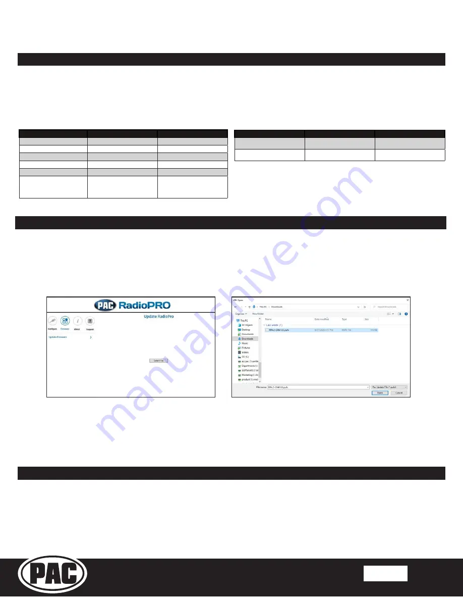
To update an interface module, open the RadioPRO PC app, connect the interface to your PC via a micro USB cable, and select 

”Firmware” and then “Update Firmware”.

Product Updates (Firmware)

Reset / Restoring Interface Factory Settings

The RadioPRO interface module can be reset to factory default settings in two ways: 
1.  By pressing and holding the programming button on the side of the module until the status LED starts blinking red. Once 

the LED starts blinking red, release the button. You must release the button while the LED is blinking red in order to perform 

the reset. This reset will restore all settings to factory defaults.

2.  In the Installer Settings on the HEIGH10. See included Installer Set Up Guide for more information.   

(

Installer Settings > Advanced Vehicle Settings > About > RadioPRO ADVANCED > Factory Reset

)

Now, select “Select File”. Finally, browse to the place where you saved the file, and select it. This will begin the updating 

process. Once finished, disconnect the interface from the PC. Repeat for each module: CH4A-SRK and PL1.

Troubleshooting

1. 

Vehicle Info icon not showing on main menu 

- After updating the Radio System Firmware, perform a master reset on the 

radio by tapping “Master Reset” in the “Installer Settings”; then, update the PAC Application APK firmware in that order. If 

the Vehicle Info icon still does not show, turn off the vehicle, open the driver door, and let it sleep for about 5 minutes, then 

restart the vehicle and check for the Vehicle Info icon again.

LED Pattern

State

Action

LED 2 solid red

Vehicle RAP / ACC Output Is On

N / A

LED 2 flashing green

SWC Activity

N / A

LED 2 flashing red

Module Resetting / Initializing

N / A

LED 1 solid green

Module Powered and Operating

N / A

LED 1 flashing amber

USB Connected

N / A

Off

No Activity

Verify key is in ignition position. 

Verify that there is 12v on the 

yellow wire and ground on the 

black wire.

CH4A-SRK Interface Module LED Diagnostics

Firmware Updates (Stinger Radio and PAC Application APK)

To update the Stinger radio firmware and PAC Application APK firmware, refer to the Installer Setup Guide for an in-depth 

walk-through on how to perform these updates on your Stinger radio unit.

LED Pattern

State

Action

LED flickering green or red

Data Communication / Normal 

Operation

N / A

Off

No Activity

Verify 10pin harness connections 

and key position

PL1 Adapter Module LED Diagnostics

Summary of Contents for HEIGH10

Page 1: ...ck Unlock SOS Assist Vehicle Location Service WiFi Hotspot 2 Not compatible with SRT or Hellcat trim levels 3 Not compatible with 2015 model year vehicles equipped with drive modes 4 Ensure that the C...

Page 2: ...SRK RadioPRO ADVANCED HDMI USB1 USB2 STINGER BLACK GRAY 10PIN 6PIN 24PIN 16PIN GPS AM FM ANT SRK CHR16 HAR 16PIN RADIO PAC Connection Stinger Connection Main Harness Connection Connections shown are a...

Page 3: ...e to remove Step 1 Lower the steering column and remove the panel by pulling outward far enough that the air vents are clear of the sub dash NOTE During removal air vents may detach from the panel the...

Page 4: ...remove the drivers side dashboard end panel Step 1 Remove the two Phillips screws securing the lower dash knee panel Step 2 The passenger side CAN junction block is located below the glove box Step 4...

Page 5: ...boot trim panel Remove the inner console cup holder trim by pulling up to release the retaining clips Step 1 Step 4 Unplug the connector on the backside of the panel and lift panel up to expose the s...

Page 6: ...e factory USB hub and remove Step 1 Referencing the front cover install the four cable ends into the back section of the USBHUB CH1B RCA 48 replacement hub Align and snap both sections together Feed t...

Page 7: ...ed and tested Once all the cable is pulled through align and snap the replacement hub into place Step 1 Step 4 Route the four media cables up from the lower dash into the radio opening area Flip the c...

Page 8: ...6V2 harness then insert the male connector on the MQS4PT36V2 harness into the now empty port on the CAN junction block Starting at the radio opening route the twisted pink wires with green connectors...

Page 9: ...1 Dodge Challenger In Vehicle Harness Connections and Preparation cont Part Three GPS Antenna and AM FM Antenna Adapter BAA22 The chime speaker can be mounted in various locations This installation u...

Page 10: ...adio Removal Remove the four screws securing the factory radio display and pull radio out to access the connectors on the back Step 3 Using a plastic trim tool release all the retaining clips holding...

Page 11: ...the drivers side dash end panel Step 1 Remove the two Phillips screws securing the side of the lower dash knee panel Pull the lower knee panel outward to release the retaining clips along the top allo...

Page 12: ...he shifter boot trim panel Remove the two screws below the lower storage bin Step 1 Step 4 Unplug the connector on the backside of the panel and lift panel up to expose the shift lever lock screw Pull...

Page 13: ...oval cont Unclip and remove the side panels on both sides of the console Open the console storage compartment and remove the coin tray and bottom rubber liner Step 1 Step 1 Unplug the factory USB conn...

Page 14: ...ack is pulled through align and snap the replacement hub into place Step 4 Flip the console over on a soft surface Bundle and route the cables towards the front the console Secure cables to the factor...

Page 15: ...ction 3 2 Dodge Charger In Vehicle Harness Connections and Preparation Part One Routing Media Hub Cables Starting at the radio opening route the twisted pink wires with green connectors on the MQS4PT3...

Page 16: ...tors and insert it into the female connector on the MQS4PT36V2 harness then insert the male connector on the MQS4PT36V2 harness into the now empty port on the CAN junction block Section 3 2 Dodge Char...

Page 17: ...that area is accessible Step 1 Remove the speaker from the mounting bracket Enlarge the mounting hole to fit over the factory stud Reinstall and tighten the bolt Remount the speaker on the bracket Fe...

Page 18: ...four screws securing the radio Pull the radio out far enough to access the connectors at the back of the radio Open the storage bin door below the climate controls Pull the climate control panel from...

Page 19: ...the drivers side dash end panel Step 1 Remove the two Phillips screws on the side of the lower dash knee panel Pull the lower knee panel outward to release the retaining clips along the top allowing a...

Page 20: ...stallation Using a plastic trim tool unclip the shifter bezel Unplug the connector on the backside and remove Step 1 Step 4 Remove the two screws securing the storage bin Step 2 Step 6 Pull the storag...

Page 21: ...Chrysler 300 Disassembly cont Part Three Center Console Removal cont Open the console storage compartment and remove the coin tray and bottom rubber liner Step 8 Remove the four screws inside the sto...

Page 22: ...ck is pulled through align and snap the replacement hub into place Step 4 Flip the console over on a soft surface Bundle and route the cables towards the front the console Secure cables to the factory...

Page 23: ...ion 2 3 Chrysler 300 In Vehicle Harness Connections and Preparation Part One Routing Media Hub Cables Starting at the radio opening route the twisted pink wires with green connectors on the MQS4PT36V2...

Page 24: ...ory male connectors and insert it into the female connector on the MQS4PT36V2 harness then insert the male connector on the MQS4PT36V2 harness into the now empty port on the CAN junction block Section...

Page 25: ...allation uses an existing hole in the metal brace on the left side of the steering column Step 1 Remove the speaker from the mounting bracket Apply the supplied two sided tape to the bottom of the bra...

Page 26: ...o the appropriate port Amplified if the vehicle has a factory amplifier Non Amplified for base audio Connect one end of the 6 Data Harness 10P 2 10P 6 HAR to the CH4A SRK Expansion Port and the other...

Page 27: ...rom the SRK CHR15H kit locate the RH and LH side brackets and spacers From the SRK CHR15H kit align and snap together mounting Bucket 1 and Bucket 2 For Challenger Charger the spacers will be installe...

Page 28: ...Module Mounting Preparation cont Part One Side Brackets and Spacers cont Part Two Interface and Radio Module Mounting Step 1 Step 2 Step 3 With the mounting assembly face down place the CH4A SRK modu...

Page 29: ...tion the radio module between the side brackets and align the left side mounting holes as shown Secure the radio module to the side bracket using two M5x10 screws from the HEIGH10 hardware Align the r...

Page 30: ...K CHR15H kit locate the RH and LH side brackets and spacers For Chrysler 300 the side brackets will be attached to Bucket 1 A B C in Position C as indicated above For Chrysler 300 the spacers will be...

Page 31: ...ties Route the other end of the display cables through the opening in the mounting assembly Leave approximately two inches of cable extending out the front From the HEIGH10 components plug the 8 pin...

Page 32: ...ect the Reverse Cam RCA on the SRK CHR16 HAR to the Reverse Camera In on the HEIGH10 24 pin AV harness From the HEIGH10 components plug the 24 pin AV harness into the radio module Part Three Radio Mod...

Page 33: ...AUX IN inputs on the HEIGH10 s 24 pin AV Harness Connect the blue GPS antenna connector to the radio module Plug the HDMI cable into the HEIGH10 Radio Module Plug the two USB cables into the HEIGH10 U...

Page 34: ...from the factory radio display to secure the assembly in place Chrysler 300 Reconnect the connector on the rear of the radio air vent trim panel and reinstall Chrysler 300 Reconnect the connector on t...

Page 35: ...up may take up to 30 seconds before the display is active Do not press the power button or turn off the vehicle during this time Once powered up refer to the included SRK CHR15H Installer Set Up Guide...

Page 36: ...ICLES cont Part Three Attaching the Display Screen cont Step 4A Chrysler 300 Behind the display frame on the top is the display locking screw opening 1 Using a magnetized Phillips screwdriver install...

Page 37: ...File Finally browse to the place where you saved the file and select it This will begin the updating process Once finished disconnect the interface from the PC Repeat for each module CH4A SRK and PL1...

Page 38: ...ranty does not cover installation expenses Attempting to service or modify our products or operate them outside their recommended usage will render this WARRANTY VOID Unless prescribed by law PAC is n...

Reviews: