Service Manual version 1008
OP 1200/1500/1700 (PC920 Intel 945G)
5-37
5.1. Display Module Assembly
The display module consists of two modules, one front bezel module and the other LCD module.
5.1.1. Front Bezel Assembly
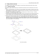
The following steps illustrate the ways to assemble touchcreen and some accessories to the front
bezel.
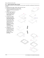
1. Refer to the figure below. There are four one-side adhesive foam sponges. Attach the four 1mm
sponge tapes to the front bezel (1). The sponge tapes act as bumpers to absorb the pressure when
the touchscreen is fixed to the front bezel.
2. There are 4 metal brackets (3) used to fix the touchscreen (2) to the front bezel. The metal
brackets have to be taped with foam sponges.
3. Put the touchscreen to the bezel with its active side facing downwards and its white flat cable at the
left side. Make sure the touch panel’s active area is aligned in the opening of the front bezel.
4. Make sure the white flat cable comes out from the underneath of the left bracket. Then, fix the
touchscreen to the front bezel with the four metal brackets and retain them together with three
PMS M3*6 screws for the up and down sides and two PMS M3*6 screws for the right and left sides.
The foam sponges are used bumpers to absorb the pressure caused by the four metal brackets
when driven tightly to the touchscreen.
FRONT BEZEL ASSEMBLY
(1)
(2)
PMS 3*6 (2)
(3)
PMS 3*6 (3)
(3)
PMS 3*6 (2)
(3)
PMS 3*6 (3)
(3)
Summary of Contents for OP 1200
Page 8: ......
Page 32: ...Service Manual version 1008 OP 1200 1500 1700 PC920 Intel 945G 4 24...
Page 79: ...Service Manual version 1008 OP 1200 1500 1700 PC920 Intel 945G 6 71...
Page 91: ...Service Manual version 1008 OP 1200 1500 1700 PC920 Intel 945G 7 83...
Page 106: ...Service Manual version 1008 OP 1200 1500 1700 PC920 Intel 945G 7 98...
Page 109: ...Service Manual version 1008 OP 1200 1500 1700 PC920 Intel 945G 7 101...
Page 112: ...Service Manual version 1008 OP 1200 1500 1700 PC920 Intel 945G 7 104...


