Service Manual version 1008
OP 1200/1500/1700 (PC920 Intel 945G)
6-59
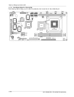
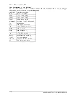
6.1.6. Connectors & Pin Assignment
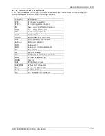
The table below lists the function of each connector on the PC920. Their corresponding pin
assignments will be shown in the following sections.
Connector
Description
ATXP1
ATX power connector
ATXP2
ATX +12V power connector
CN1
Power connector for touchscreen
PWR1
Power Output Connector
INV1
LCD Inverter connector
LCD1
LCD connector
USB1,2
USB1&USB2 port connector
IDE1
PATA connector For CD-ROM
SATA1~4
SATA1~4 connector
COM2
Serial port 2
COM3
Serial port 3 (for touchscreen)
CD1
CD audio In
IR1
IR/CIR connector
CN4
KB/Mouse/Speaker/LED connector
EISA1
PCI/ISA expansion slot
IOINF1
I/O slot
FAN1
CPU FAN connector
FAN2/FAN3
System FAN connector
CN3
ATX power ON Switch
RST1
Reset connector
CN2
EXT. LAN wake up connector
Summary of Contents for OP 1200
Page 8: ......
Page 32: ...Service Manual version 1008 OP 1200 1500 1700 PC920 Intel 945G 4 24...
Page 79: ...Service Manual version 1008 OP 1200 1500 1700 PC920 Intel 945G 6 71...
Page 91: ...Service Manual version 1008 OP 1200 1500 1700 PC920 Intel 945G 7 83...
Page 106: ...Service Manual version 1008 OP 1200 1500 1700 PC920 Intel 945G 7 98...
Page 109: ...Service Manual version 1008 OP 1200 1500 1700 PC920 Intel 945G 7 101...
Page 112: ...Service Manual version 1008 OP 1200 1500 1700 PC920 Intel 945G 7 104...

